

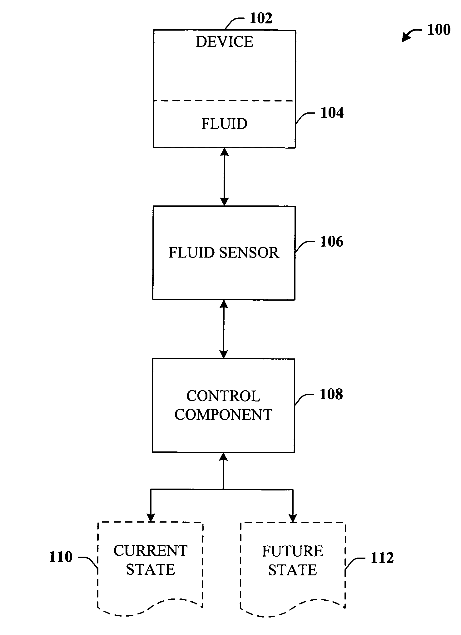
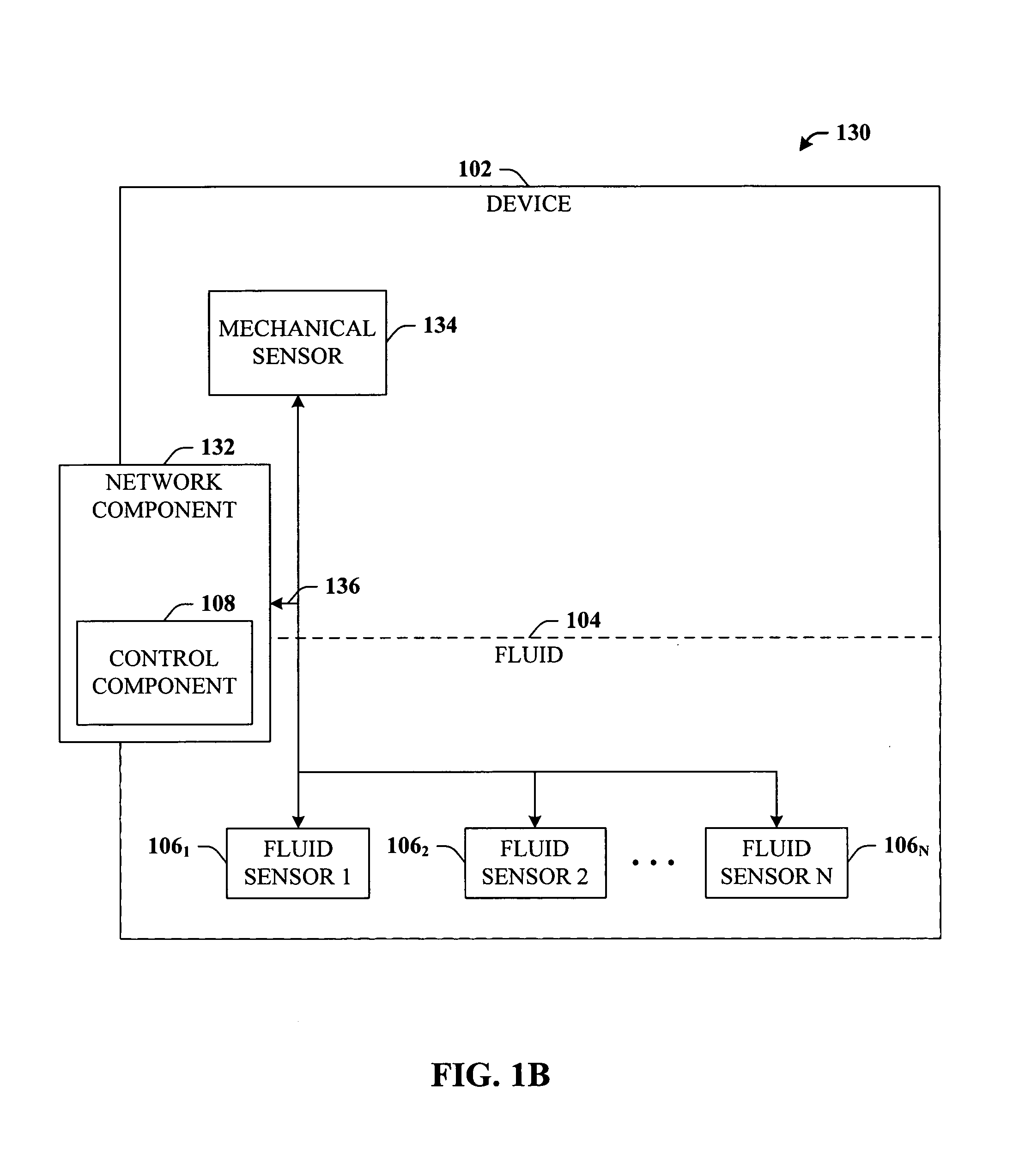
Intelligent fluid sensor for machinery diagnostics, prognostics, and control
a fluid sensor and intelligent technology, applied in the direction of instruments, mechanical equipment, engine dialectricum, etc., can solve the problems of lubrication breakdown, lubrication loss, lubrication loss, etc., to reduce the bandwidth requirements of the network, eliminate the cost of wiring sensors, and improve performance.
- Summary
- Abstract
- Description
- Claims
- Application Information
AI Technical Summary
Benefits of technology
Problems solved by technology
Method used
Image

Examples
case b
RoCo or RpCdl≧RoCo
[0148]In the case where RpCdl is not significantly different from RoCo, such as when Rp=6.0×10⁹Ω, Cdl=6.0×10⁻¹¹ F, Ro=6.5×10⁹Ω and Co=5.0×10⁻¹² F, the frequency response of the system is similar to the response of a single parallel RC circuit as shown in FIG. 15. The Nyquist plot in FIG. 16 shows the complex-plane curve as a modified form of semicircular shape. In this case, the circle 1602 indicates the impedance at 0.01 Hz and the diagram indicates that the frequency response of the system could be composed of, at least two semicircles. The semicircles exhibit a high overlapping degree. By considering the frequency responses, it is evident that the component log|1+jωCoRo| mainly contribute to the frequency response of the system in the high frequency range. Therefore, the capacitance of the bulk lubricant layer can be estimated by extrapolating the magnitude curve with slope of −1 to the log |Z| axis at f=0.16 Hz. Then log |Rp+Ro| can be estimated from the magnit...
PUM
| Property | Measurement | Unit |
|---|---|---|
| conductivity | aaaaa | aaaaa |
| voltage | aaaaa | aaaaa |
| applied voltage | aaaaa | aaaaa |
Abstract
Description
Claims
Application Information