Serpentine microcircuit cooling with pressure side features

a technology of side features and serpentine, which is applied in the direction of liquid fuel engines, marine propulsion, vessel construction, etc., can solve the problems of blade material melting and burning away, and achieve the effect of increasing the local pressure source and increasing the heat pick-up ability

Active Publication Date: 2009-09-01
RTX CORP
View PDF5 Cites 8 Cited by
  • Summary
  • Abstract
  • Description
  • Claims
  • Application Information

AI Technical Summary

Benefits of technology

[0010]In accordance with the present invention, there is provided two solutions. The first is to include communication holes between the internal cavity and the microcircuit third leg so as to have an increased source of local pressure. It should be noted that the flow inside the inner cavity is high compared to that on the microcircuit legs with many loss mechanisms. The second is to include a set of features which are used to locally accelerate the flow and increase the ability for heat pick-up in the third leg of the pressure side circuit.
[0012]Further, in accordance with the present invention, there is provided a turbine engine component having an airfoil portion with a pressure side and a suction side, a first microcircuit embedded in a wall forming the pressure side, said first microcircuit having an inlet leg, an intermediate leg, and an outlet leg, and means in the outlet leg for locally accelerating cooling flow in the outlet leg and for increasing heat pick-up ability.

Problems solved by technology

In that case, the blade material will certainly melt and burn away.

Method used


Image

  • Serpentine microcircuit cooling with pressure side features
  • Serpentine microcircuit cooling with pressure side features
  • Serpentine microcircuit cooling with pressure side features

Examples


Embodiment Construction

)

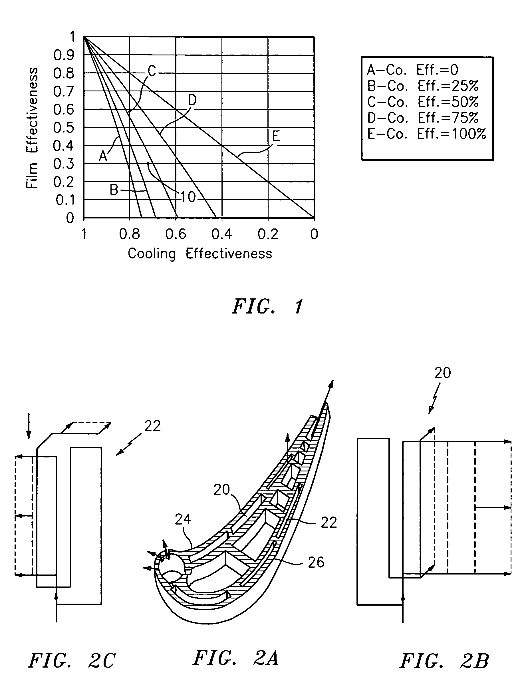
[0024]Referring now to FIG. 5, there is shown an airfoil portion 30 of a turbine engine component. The turbine engine component may comprise a turbine blade or any other component having an airfoil portion.

[0025]The airfoil portion 30 has a pressure side 32 formed by a pressure side wall 34 and a suction side 36 formed by a suction side wall 38. The airfoil portion 30 further has a plurality of internal cavities 40 through which a cooling fluid flows. Embedded in the pressure side wall 34 is a serpentine cooling microcircuit 42. Embedded in the suction side wall 38 is a serpentine cooling microcircuit 44.

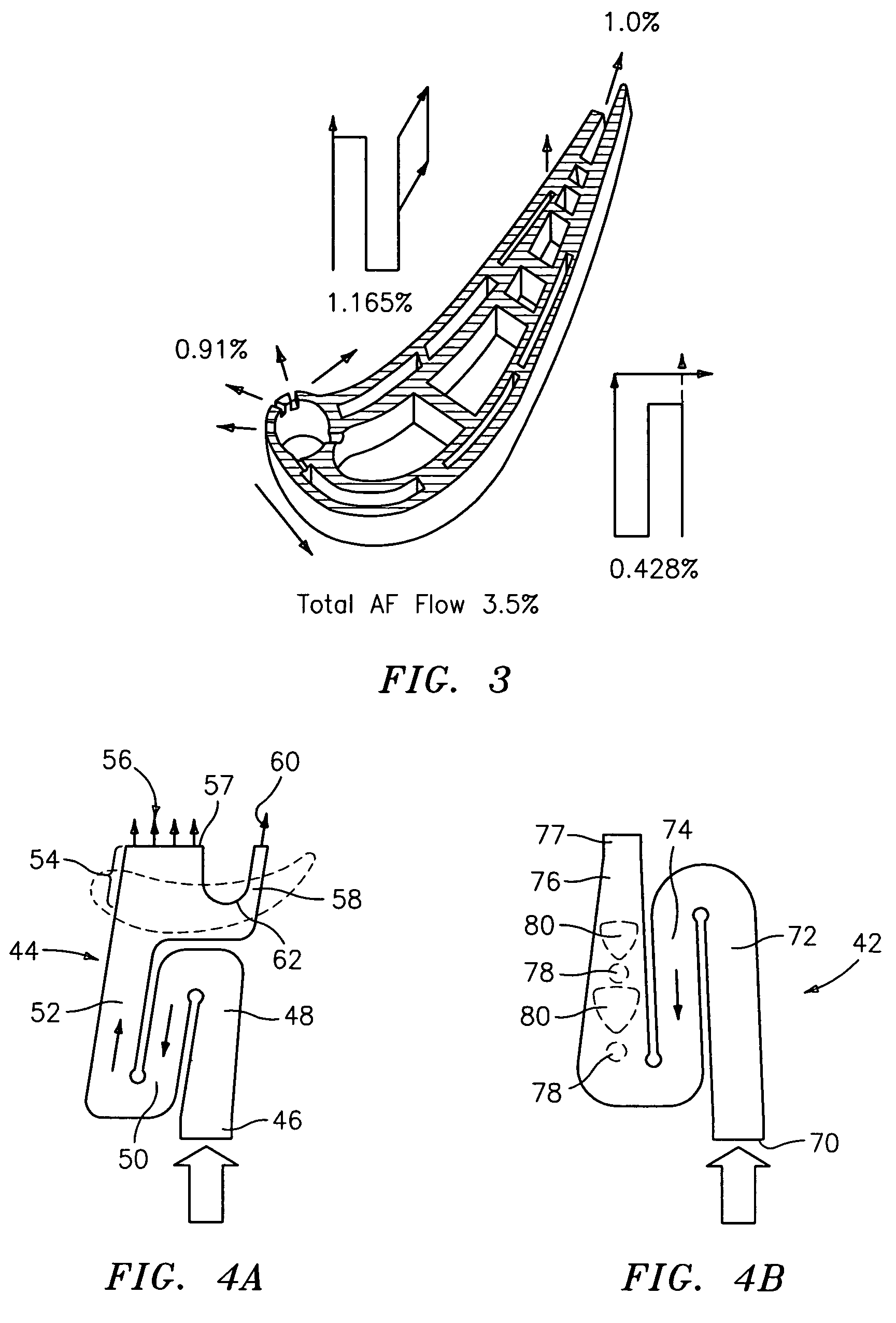
[0026]Referring now to FIG. 4A, there is shown a schematic representation of the serpentine cooling microcircuit 44. The serpentine cooling microcircuit 44 includes an inlet 46 which communicates with one of the internal cavities 40. The microcircuit 44 further includes an inlet leg 48, an intermediate leg 50, and outlet leg 52. The outlet leg 52 has a first portion 54 with a plura...


PUM


Abstract

In accordance with the present invention, there is provided a turbine engine component having an airfoil portion with a pressure side and a suction side, a first microcircuit embedded in a wall forming the pressure side, an internal cavity containing a supply of cooling fluid, the first microcircuit having an inlet leg, an intermediate leg, and an outlet leg, and a plurality of communication holes between the internal cavity and the outlet leg. In a preferred embodiment, the outlet leg is provided with at least one set of features for locally accelerating cooling flow in the outlet leg and for increasing heat pick-up ability.

Description

BACKGROUND[0001](1) Field of the Invention[0002]The present invention relates to a turbine engine component having an airfoil portion with a serpentine cooling microcircuit embedded in the pressure side, which serpentine cooling microcircuit is provided with a way to increase coolant pressure and a way to accelerate local cooling flow and increase the ability to pick-up heat.[0003](2) Prior Art[0004]The overall cooling effectiveness is a measure used to determine the cooling characteristics of a particular design. The ideal non-achievable goal is unity, which implies that the metal temperature is the same as the coolant temperature inside an airfoil. The opposite can also occur when the cooling effectiveness is zero implying that the metal temperature is the same as the gas temperature. In that case, the blade material will certainly melt and burn away. In general, existing cooling technology allows the cooling effectiveness to be between 0.5 and 0.6. More advanced technology such a...

Claims


Application Information

Patent Timeline
Patent Type & Authority Patents(United States)
IPC IPC(8): F01D5/18
CPCF01D5/187F05D2260/2214F05D2250/185
Inventor CUNHA, FRANCISCO J.
Owner RTX CORP
Why Eureka
Try Eureka