Metal component treated by putting sublayers in compression, and method of obtaining such a component

a metal component and sublayer technology, applied in the field of metal component treatment, can solve the problems of long implementation time, inability to scan the entire surface to be treated with laser spots in a single sequence, and inability to achieve the effect of reducing the effect of tensile stress and preventing large tensile gradients

Active Publication Date: 2009-09-01
SN DETUDE & DE CONSTR DE MOTEURS DAVIATION S N E C M A
View PDF8 Cites 22 Cited by
  • Summary
  • Abstract
  • Description
  • Claims
  • Application Information

AI Technical Summary

Benefits of technology

[0022]Preferably, the two zones are adjacent, thus creating a progressive residual stress gradient. Unlike in components comprising zones treated by laser shock peening bordered by adjacent zones not in compression, no adjacent portions are created which are subjected to a sudden jump in stress in which cracks may appear. Moreover, any deformation in components such as thin blades generated by these sudden changes in stress is avoided.

Problems solved by technology

However, this laser shock peening process is relatively tedious to implement.
Furthermore, it is not possible to scan the entire surface to be treated with laser spots in a single sequence, even less so as the coating is destroyed by the laser impact beyond the area of the spot.
The implementation of this technique is lengthy and complex and, as a consequence, costly.
However, other parts of the blade are not free of damage.
For the abovementioned reasons, it would not be economically advantageous to treat an extensive area of the blade by laser shock peening.
Moreover, it has been found that zones treated by peening as intense as laser shock peening result in local tensile stresses on their periphery, which balance out all the stresses.

Method used


Image

  • Metal component treated by putting sublayers in compression, and method of obtaining such a component
  • Metal component treated by putting sublayers in compression, and method of obtaining such a component

Examples


Embodiment Construction

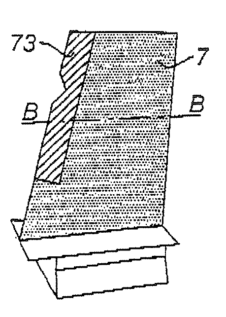
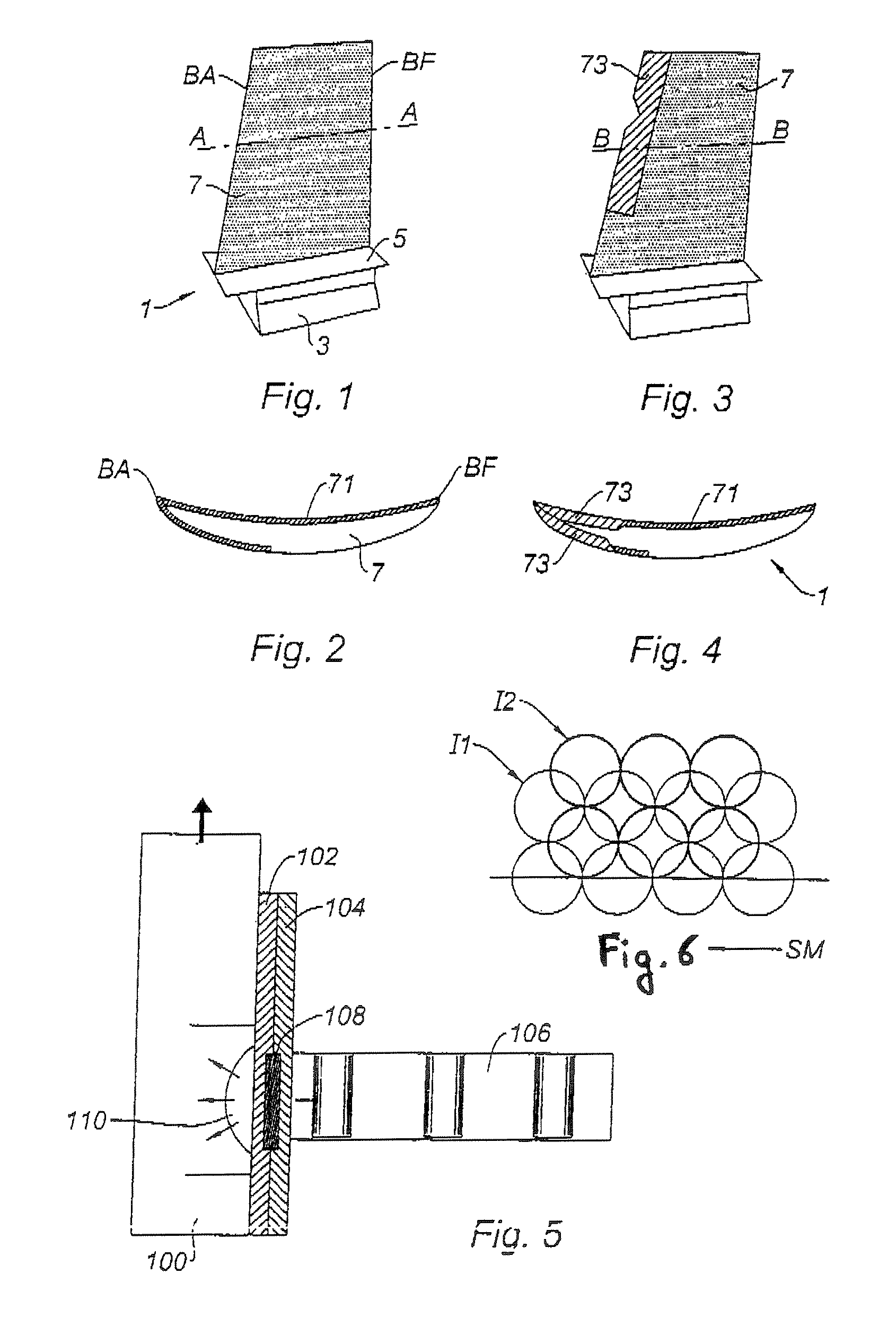
[0032]As may be seen in FIG. 1, a blade 1 comprises a root 3, a platform 5 and an airfoil 7. The blade is mounted via the root 3 on the periphery of a rotor disk in a suitable housing. The platform provides the continuity of the annular duct in which the gas stream is guided.

[0033]The airfoil 7 of aerodynamic shape is swept by the gas stream. It is this part of the blade that is exposed to the external stresses, which have an effect on the lifetime. The leading edge LE and trailing edge TE are possibly exposed to violent shocks, such as from foreign bodies ingested by the motor and striking the fan blades. These impacts may have a depthwise effect in the peripheral zones of the airfoil. Other impacts, such as those of erosive particles, are more superficial, but are found in more extended zones of the airfoil in the form of scratches and abrasions. The residual stresses generated by the peening help to limit damage and crack propagation and to increase the fatigue resistance—their p...


PUM

PropertyMeasurementUnit
thicknessaaaaaaaaaa
depthsaaaaaaaaaa
compressive stressesaaaaaaaaaa

Abstract

The invention relates to a metal component comprising at least a first zone treated by putting layers beneath the surface thereof in compression. It is characterized in that it comprises at least a first layer put in compression by shot peening and a deeper subjacent second layer put in compression by laser shock peening.The component may be a turbomachine blade. According to the method, said zone is firstly treated by prestress shot peening followed by compression treatment by laser shock peening.

Description

BACKGROUND OF THE INVENTION[0001]The present invention relates to the field of the treatment of metal components by putting layers subjacent the surface of the components in compression. The invention relates in particular to the field of aeronautical turbomachines, where such a technique is used in order to improve the lifetime of the components subjected to high stresses, both mechanical and thermal. Thus, in particular the blades, rotor disks or blisks (one-piece bladed disks) are treated.DESCRIPTION OF THE PRIOR ART[0002]Several techniques for putting internal layers of metal components in compression are known. According to a first conventional technique, said layers are put in compression by spherical shot peening, the purpose of which is to create residual stresses on the surface and in the sublayers of the metal parts. The purpose of this compressive stress is to delay the appearance of cracks or to close up existing crack initiators. As a result, their mechanical behavior i...

Claims


Application Information

Patent Timeline
Patent Type & Authority Patents(United States)
IPC IPC(8): C21D1/00B24B39/00C21D7/06
CPCB21D53/78B23P9/00B24C1/10F01D5/005F01D5/286Y10T29/479Y02T50/67Y02T50/673F05D2230/90F05D2230/80F04D29/324Y02T50/60
Inventor VIGNEAU, JOEL OLIVIER ALFRED ABEL
Owner SN DETUDE & DE CONSTR DE MOTEURS DAVIATION S N E C M A
Why Eureka
Try Eureka