Supported catalysts with controlled metal cluster size

a technology of supported catalysts and clusters, which is applied in the field of catalysts, can solve the problems of poor control over metal particle size, geometry, metal dispersion, etc., and achieve the effect of precise control of particle size, particle spacing, and particle size distribution in the catalys

Active Publication Date: 2009-09-01
UNIVERSITY OF SOUTH CAROLINA +1
View PDF5 Cites 17 Cited by
  • Summary
  • Abstract
  • Description
  • Claims
  • Application Information

AI Technical Summary

Problems solved by technology

However, the results of such preparation methods often include poor control over metal particle size, geometry, and metal dispersion.
The above referenced techniques lack the ability to precisely control the particle size, particle spacing, and size distribution of particles in a catalyst.

Method used


Image

  • Supported catalysts with controlled metal cluster size
  • Supported catalysts with controlled metal cluster size
  • Supported catalysts with controlled metal cluster size

Examples


example 1

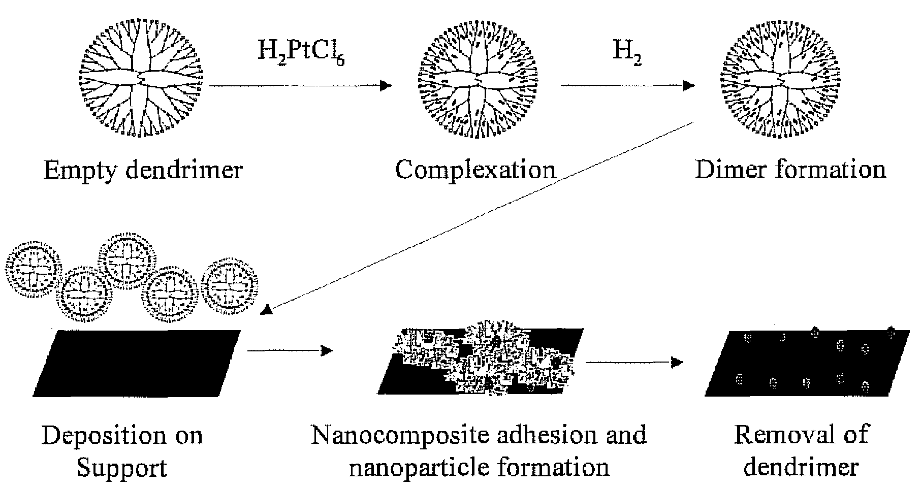
[0029]An appropriate amount of a 2.5×10⁻² M aqueous solution of H2PtCl6.6H2O was added under nitrogen flow to a 0.17 M aqueous solution of G4OH dendrimer in order to obtain the desired molar ratio of metal to G4OH dendrimer. The mixture was stirred under nitrogen flow for 3 days to allow for the complexation of Pt cations in the solution with the functional groups of the dendrimer. The dendrimer-Pt complexes were subsequently mixed with a freshly prepared NaBH4 solution (molar ratio of BH4− to metal cation of 8 to 1) in order to better facilitate reduction of the incorporated Pt cations. Following this step, the Pt-dendrimer metal nanocomposites were deposited onto previously calcined (in air, overnight at 500° C.) γ-Al2O3 via standard wet impregnation. The solvent was allowed to evaporate by stirring the resulting slurry at ambient conditions.

example 2

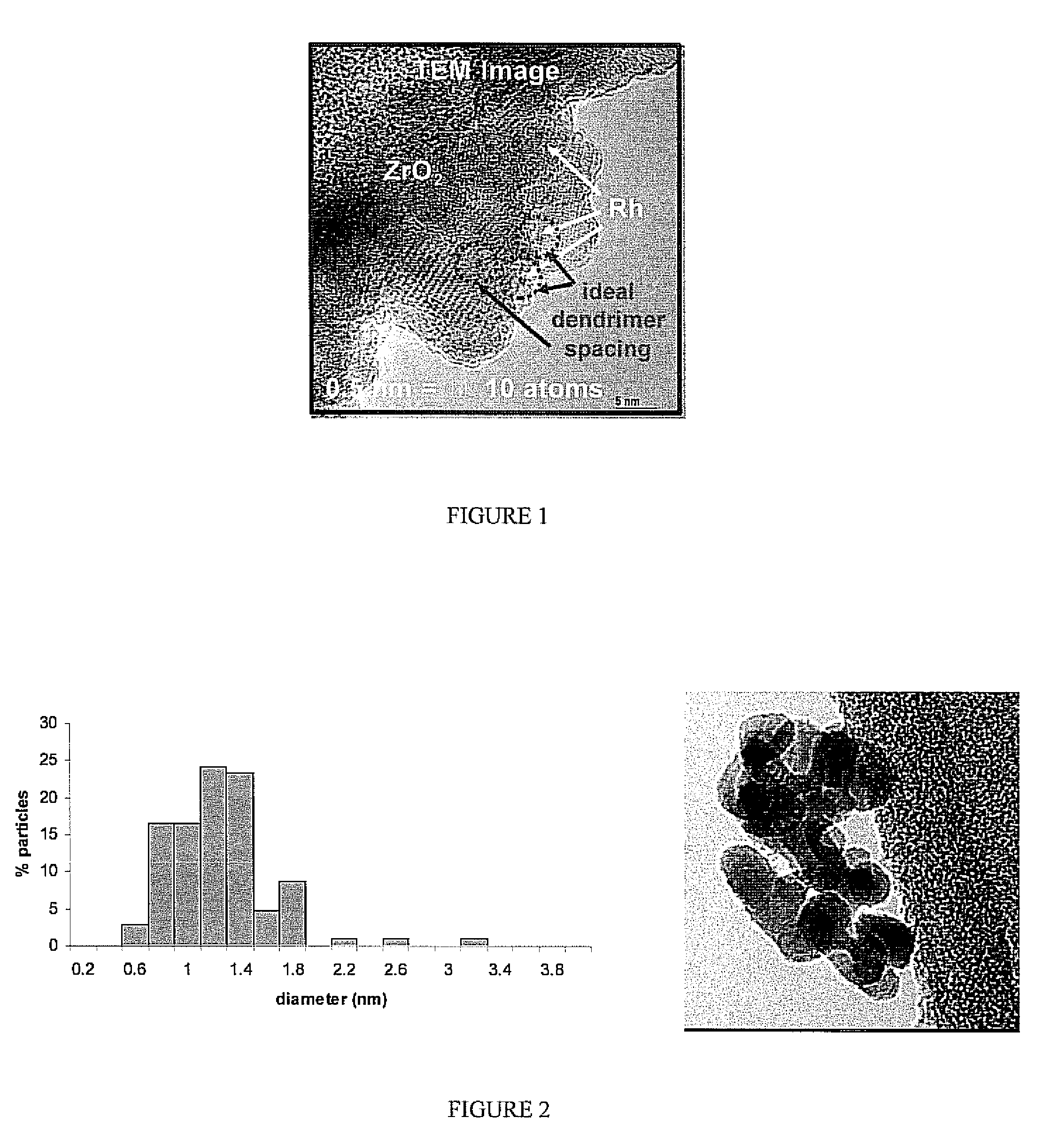
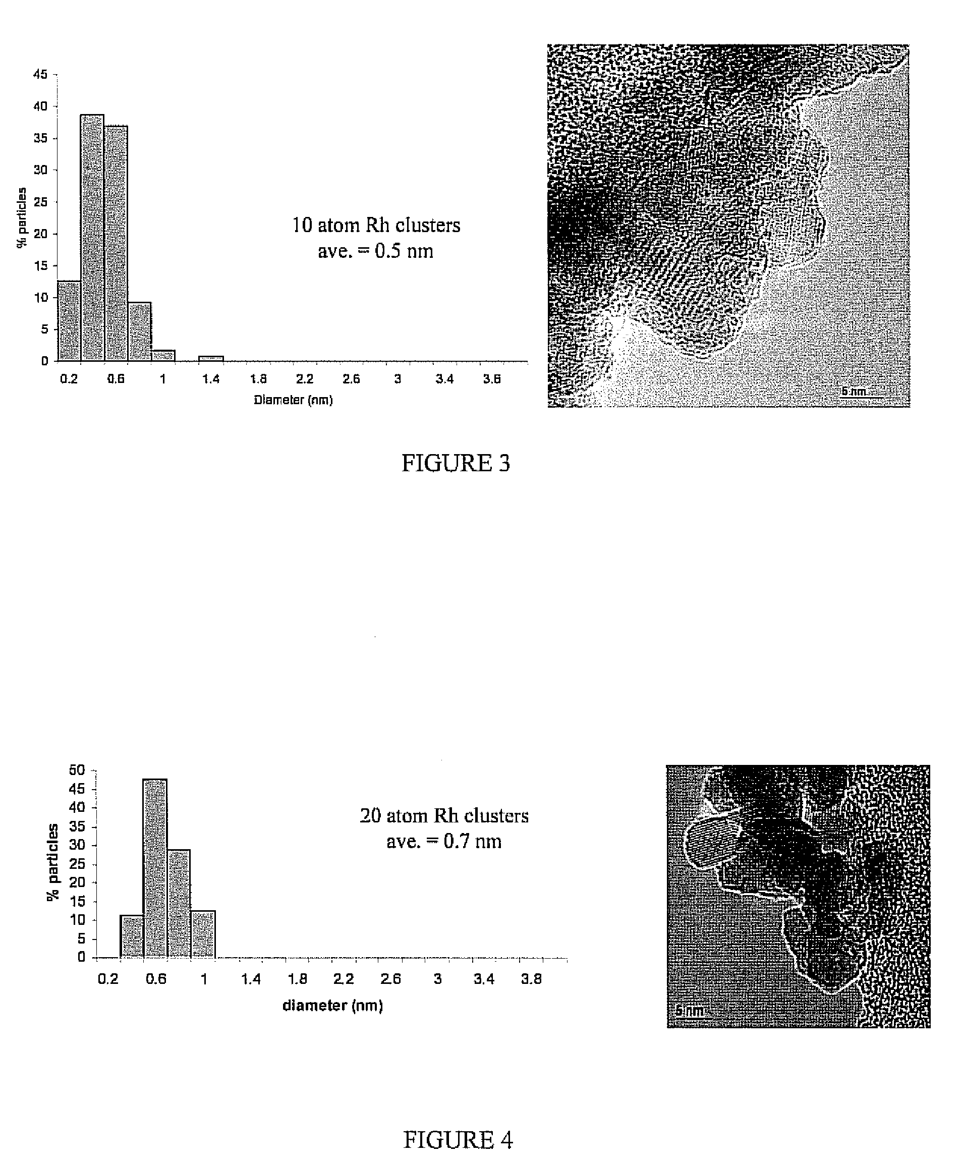
[0030]This approach has been extended to the synthesis of Rh-dendrimer nanocomposites. Instead of 3 days of metal-dendrimer complexation, the Rh samples required only 1 day for incorporation within the dendrimer. Similarly, rhodium-dendrimer-metal nanocomposites were deposited onto a commercial ZrO2 support (uncalcined). The nominal metal loading of both supported metal catalysts used in this study was 1 wt %.

example 3

[0031]Pd-dendrimer nanocomposites have also been synthesized, and the process is identical to that of preparing Rh-dendrimer metal nanocomposites. Complexation of the palladium precursor, K2PdCl4, requires only 1 day for incorporation within the dendrimer. After reduction in solution with NaBH4, the resulting Pd-dendrimer nanocomposites were deposited onto calcined aluminum oxide.

[0032]In all of the examples, the dendrimer was removed as a final step in forming a catalyst. Various conditions for different metal, dendrimer and support materials may be used to remove the dendrimer. For example a sequential oxidation at an elevated temperature followed by a reduction at an elevated temperature may be used by the process. The temperature of the oxidation may range from 300° C. to 500° C. for the various support materials, with various exposure times. In one aspect, the oxidation may be at 420° C. for one hour in a 10% O2 / He atmosphere Al2O3 and ZrO2 supports and greater than 300° C. for...


PUM

PropertyMeasurementUnit
sizeaaaaaaaaaa
temperatureaaaaaaaaaa

Abstract

There is disclosed a process for producing a catalyst. The process includes the steps of: a) combining a dendrimer polymer and metal salt in solution forming a metal ion complex; b) exposing the metal ion complex to a reducing environment forming a dendrimer metal nanocomposite; c) depositing the dendrimer metal nanocomposite onto a catalyst support material; d) removing a solvent from the dendrimer metal nanocomposite forming metal clusters; and e) removing the dendrimer polymer forming a catalyst. Additionally, there is disclosed a catalyst having a catalytic metal deposited on a substrate. The catalytic metal is formed in clusters having a size of from 2 to 150 atoms. In another aspect, the clusters may have a spacing of from 2 to 100 nanometers between adjacent metal clusters. Further, in another aspect, the metal clusters which comprise the catalyst have a size distribution in which 70% of the clusters are within 0.6 nm of the average diameter and 99% of the particles are within 1.5 nm of the average diameter.

Description

FIELD OF THE INVENTION[0001]The invention relates to catalysts and a process for producing catalysts.BACKGROUND OF THE INVENTION[0002]Traditional methods for synthesizing heterogeneous catalysts often involve the deposition of an inorganic salt precursor onto a porous support via incipient wetness impregnation or co-precipitation techniques, followed by various drying and post-deposition steps. Attempts to control the size of the resulting metal particles are often made through the optimization of precursor solution conditions and subsequent time / temperature thermal treatments. However, the results of such preparation methods often include poor control over metal particle size, geometry, and metal dispersion. The above referenced techniques lack the ability to precisely control the particle size, particle spacing, and size distribution of particles in a catalyst.[0003]There is therefore, a need in the art for a catalyst with a tightly controlled particle size, spacing and distributi...

Claims


Application Information

Patent Timeline
Patent Type & Authority Patents(United States)
IPC IPC(8): B01J31/00B01J23/40B01J23/42B01J23/44B01J37/00C08F4/02C08F4/60B01J21/00B01J23/00B01J23/10
CPCC07C45/50B01J23/40B01J23/42B01J23/44B01J23/464B01J23/63B01J35/0013B01J35/006B01J37/0018B01J37/0213B01J37/16C07C47/02B01J21/04B01J21/06B01J21/066B01J37/0201
Inventor FANSON, PAUL T.HIRATA, HIROHITOAMIRIDIS, MICHAEL D.WILLIAMS, CHRISTOPHER T.DEUTSCH, DAVID S.SIANI, ATTILIOMATSUMOTO, SHINICHI
Owner UNIVERSITY OF SOUTH CAROLINA
Why Eureka
Try Eureka