Mass spectrometer

a mass spectrometer and mass spectrometer technology, applied in mass spectrometers, separation processes, dispersed particle separation, etc., can solve the problems of air evacuation, troublesome and costly operation, and prone to increase in machining costs, so as to reduce kinetic energy, the effect of high degree of accuracy and efficient sending

Active Publication Date: 2009-09-01
SHIMADZU CORP
View PDF10 Cites 14 Cited by
  • Summary
  • Abstract
  • Description
  • Claims
  • Application Information

AI Technical Summary

Benefits of technology

[0010]In view of the above problems, it is a principal object of the present invention to provide an ion optical system for converging ions and transporting the ions to a subsequent stage in a mass spectrometer, at a lower cost as compared with the conventional system.
[0012]In the mass spectrometer of the present invention, each of the number n of electrodes constituting the ion optical system is a metal plate member instead of a metal block as in the conventional ion optical system. Thus, the metal plate member can be formed, for example, by subjecting a large sheet metal to shearing, cutting or punching. Specifically, a metal plate member having a given shape can be readily formed by a wire-EDM process, a laser machining process or a shearing process. Thus, there is no need to taking time for forming each of the electrodes. In addition, a cable for applying an AC voltage or a DC voltage can be fixed to the electrode by a low-cost process, such as soldering. This makes it possible to reduce a cost of the ion optical system as compared with the conventional ion optical system.
[0013]In the ion optical system of the mass spectrometer of the present invention, each of the thin edge surfaces of the number n of metal plate members is disposed to face the ion optical axis, and an electric field formed in an internal space based on a potential between the edge surface and each edge region of opposite side surfaces on both sides of the edge surface acts on ions. While an electric field around the edge surface is not exactly sufficient to converge ions due to a small width of the edge surface, the electric field has an adequate shape at a position away from the edge surface and closer to the ion optical axis. Therefore, an appropriate voltage can be applied to the electrodes to fulfill an adequate function of sending ions to a subsequent stage while preventing spreading of the ions.
[0014]Each of the metal plate members is disposed to extend along the ion optical axis. Thus, a relatively wide space can be ensured between the two metal plate members adjacent to each other around the ion optical axis. This makes it possible to provide enhanced communication between internal and external spaces of the ion optical system so as to avoid the problem about the need for taking wasted time to evacuate air of an intermediate vacuum chamber provided with the ion optical system, or the like.
[0018]In particular, the laser machining process allows a sheet metal to be cut in various shapes, such as a sine-wave shape, a saw-tooth shape or a rectangular-wave shape, readily with a high degree of accuracy. The electrode formed of a metal plate member having such a particular shape can temporarily capture ions, in addition to accelerating and decelerating the ions in the internal space of the ion optical system as described above.
[0019]While the ion optical system in the mass spectrometer of the present invention may be used simply for introducing ions into the mass separator, such as a quadrupole mass filter, it may be conveniently used in a so-called tandem mass spectrometer. Specifically, first and second mass separators are disposed, respectively, in preceding and subsequent stages relative to the ion optical system, and the ion optical system has gas for collision-induced dissociation (hereinafter referred to as “collision-induced dissociation gas”) is introduced into the internal space of. The first mass separator is operable to separate and select ion species having a specific mass number. Then, the selected ion species are subjected to collision—induced dissociation in the internal space of the ion optical system, and created ions are sent to the second mass separator. In this tandem mass spectrometer, while the ions introduced into the internal space of the ion optical system and reduced in kinetic energy due to collision with the collision-induced dissociation gas are likely to stagnate, ions created by the collision-induced dissociation can be accelerated in the above manner to adequately pass through the internal space of the ion optical system, and efficiently sent to the second mass separator.

Problems solved by technology

Thus, a machining cost is apt to increase.
This operation is troublesome and costly.
Further, in the ion optical system using the rod electrodes, a communication space between an internal space surrounded by the rod electrodes and an external space becomes narrow to cause a problem about a difficulty in evacuating air from the internal space of the ion optical system, and the need for taking time to evacuate the internal space to have given vacuum.

Method used


Image

  • Mass spectrometer
  • Mass spectrometer
  • Mass spectrometer

Examples


Embodiment Construction

[0028]With reference to FIGS. 1 to 3, a mass spectrometer according to one embodiment of the present invention will now be described. Except that an ion optical system to be disposed in the intermediate vacuum chamber 18 in FIG. 6 is different from that in FIG. 6, a fundamental structure of the mass spectrometer according to this embodiment is the same as that illustrated in FIG. 6. The difference will be specifically described below.

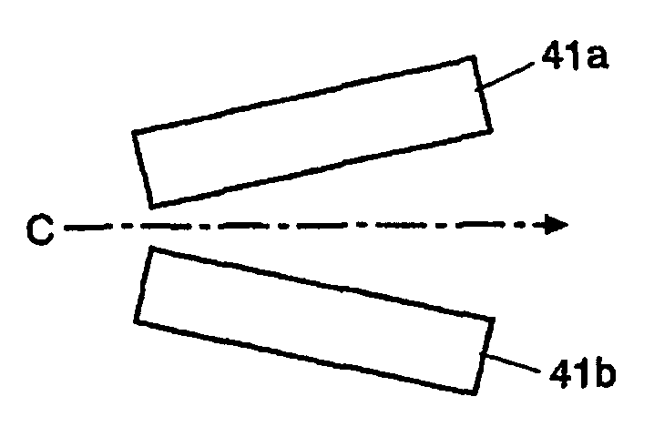
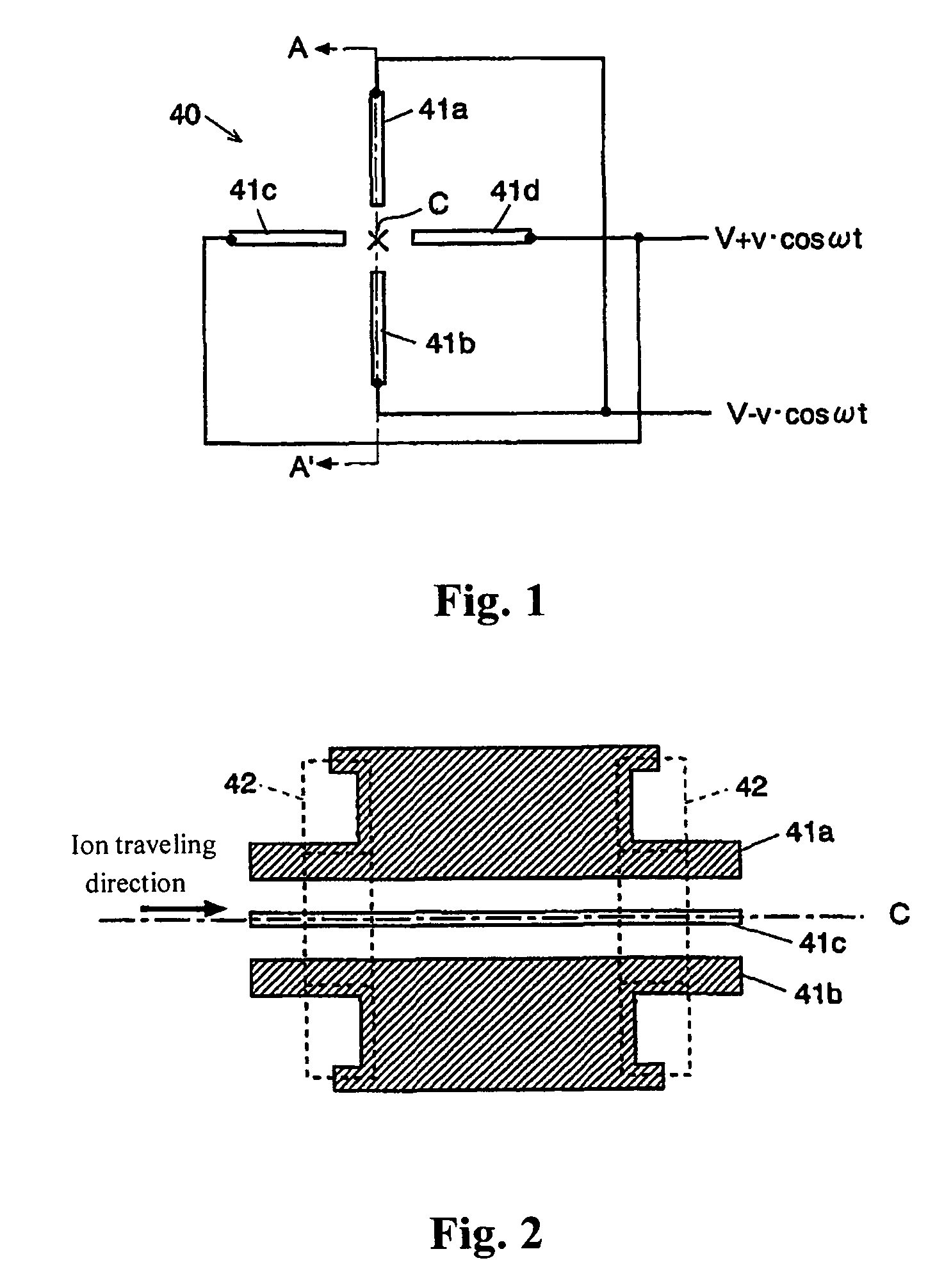
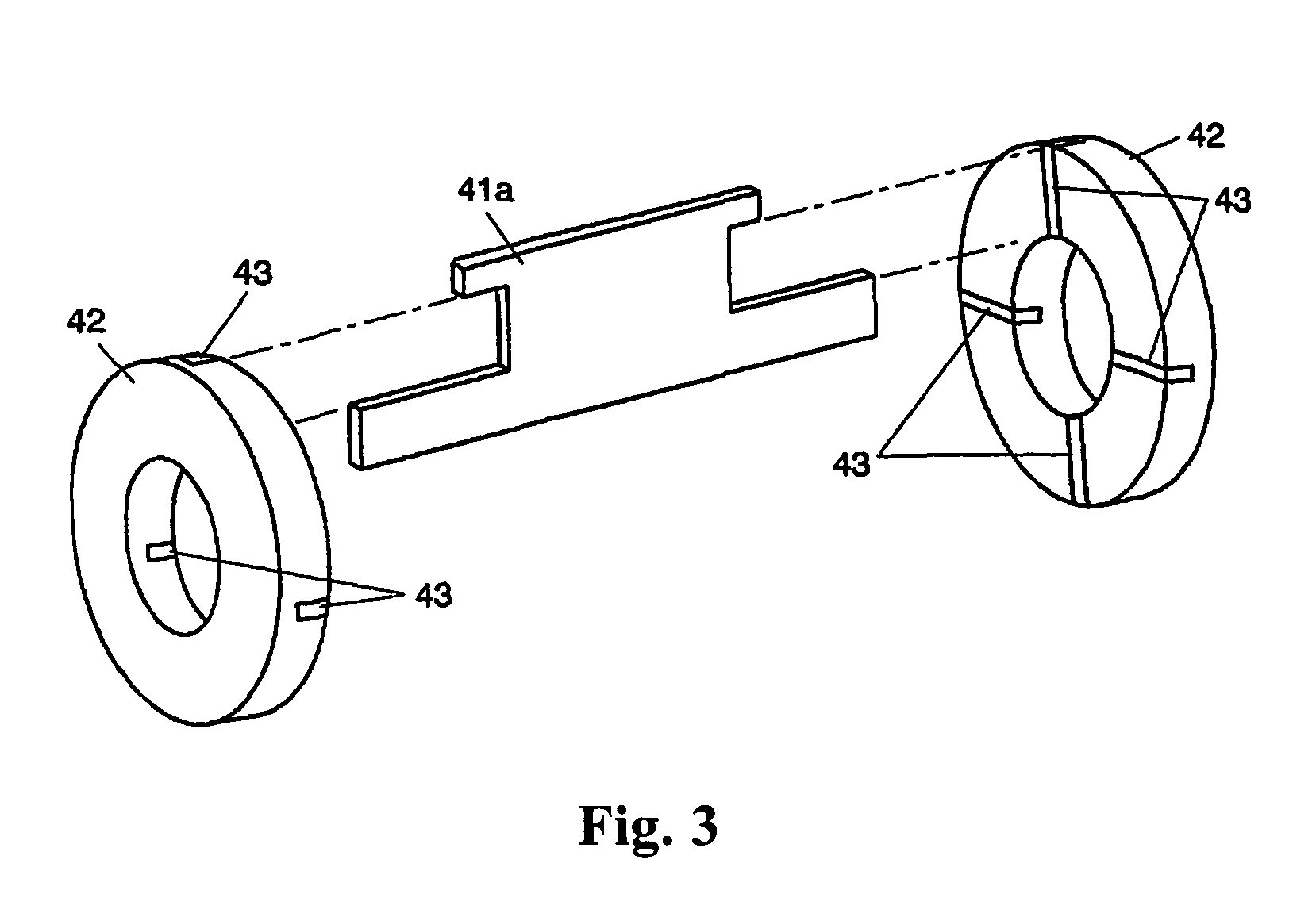
[0029]FIG. 1 is a schematic diagram showing an ion optical system 40 serving as a second lens electrode in the mass spectrometer according to this embodiment, viewed from the side of an ion incident end of the ion optical system. FIG. 2 is a sectional view taken along the line A-A′ in FIG. 1, and FIG. 3 is a fragmentary assembling diagram of the ion optical system.

[0030]The ion optical system 40 in this embodiment comprises four electrodes 41a, 41b, 41c, 41d each formed of a metal plate member having a given shape. Each of the electrodes 41a, 41b, 41c, ...


PUM


Abstract

Disclosed is a mass spectrometer, which includes an ion optical system for converging ions and transporting the ions to a subsequent stage. Instead of a conventional rod-shaped electrode, the ion optical system includes an electrode formed of a thin metal plate member. Specifically, each of four electrodes 41a to 41d formed of the metal plate members has an edge surface facing an ion optical axis C and extends along the ion optical axis C. Further, the electrodes 41a to 41d are disposed around the ion optical axis C in a radial pattern while keeping an angle of 90° between the adjacent electrodes. The present invention can provide the ion optical system at a lower cost.

Description

BACKGROUND OF THE INVENTION[0001]1. Field of the Invention[0002]The present invention relates to a mass spectrometer, and more specifically to an ion-optical system for converging ions and transporting the ions to a subsequent stage in a mass spectrometer.[0003]2. Description of the Related Art[0004]Generally, in a liquid chromatograph mass spectrometer (LC / MS) which is a combination of a liquid chromatograph (LC) and a mass spectrometer (MS), an atmospheric pressure ionization process, such as an electrospray ionization (ESI) process or an atmospheric pressure chemical ionization (APCI) process, is used. In this spectrometer, while an ionization chamber is in an atmosphere of approximately atmospheric pressure, an analysis chamber internally equipped with a detector and a mass spectrometer, such as a quadrupole mass filter, is required to be maintained in a vacuum state. For this purpose, a differential evacuation system comprising one or more intermediate vacuum chambers provided ...

Claims


Application Information

Patent Timeline
Patent Type & Authority Patents(United States)
IPC IPC(8): B01D59/44
CPCH01J49/063
Inventor MUKAIBATAKE, KAZUO
Owner SHIMADZU CORP
Why Eureka
Try Eureka