Semiconductor device with enhanced breakdown voltage

a technology of semiconductor devices and breakdown voltages, applied in semiconductor devices, transistors, electrical apparatus, etc., can solve problems such as unstable breakdown voltages, increase in the forming area of field plate structures, and unstable breakdown voltages, so as to suppress the deterioration of breakdown voltages and relieve electric field concentrations

Active Publication Date: 2009-09-01
MITSUBISHI ELECTRIC CORP
View PDF10 Cites 9 Cited by
  • Summary
  • Abstract
  • Description
  • Claims
  • Application Information

AI Technical Summary

Benefits of technology

[0011]Because the intermediate potential applying means is provided locally in a partial region on the insulating film, the width of the remaining region on the chip peripheral structure can be reduced. And because a high breakdown voltage on the chip peripheral structure is achieved by the intermediate potential electrode, deterioration of the breakdown voltage can be suppressed even with the width reduction of the chip peripheral structure. In short, this invention helps achieve a high degree of integration and size reduction of the semiconductor device while maintaining the breakdown voltage.
[0013]Because the back-to-back diode is provided locally in a partial region on the insulating film, the width of the remaining region on the chip peripheral structure can be reduced. Further, although it is difficult to match potentials between the back-to-back diode and the guard ring in the region where the back-to-back diode is formed, the line-shaped impurity region being formed in that region relieves electric field concentration, thus suppressing deterioration of the breakdown voltage.
[0015]Because the back-to-back diode positioned above the guard ring holds a voltage of 60 V or below, a potential difference between the guard rings and the back-to-back diode is suppressed, thereby relieving electric field concentration and suppressing deterioration of the breakdown voltage.

Problems solved by technology

However, being formed on a substrate, a field plate is susceptible to polarization of a resin and the like for molding a chip top surface (mold polarization), which leads to breakdown voltage fluctuations and so on to cause the breakdown voltage to be unstable.
Besides, in a semiconductor device structure combining a back-to-back diode and guard ring, a potential difference develops easily between a region below the back-to-back diode and the remaining region in the guard ring, which leads to an unstable breakdown voltage.
In short the back-to-back diodes are formed on the whole periphery of the chip, giving a problem of an increase in forming area for the field plate structure.
This makes the potential at the chip peripheral portion unstable, which results in an unstable breakdown voltage easily.
However, the above problems (increase in forming area for the field plate structure, and instability of the potential at the chip peripheral portion) become more pronounced with the widening of the diodes, and a too much widening will make it difficult to maintain a high breakdown voltage or will increase a leakage current.

Method used


Image

  • Semiconductor device with enhanced breakdown voltage
  • Semiconductor device with enhanced breakdown voltage
  • Semiconductor device with enhanced breakdown voltage

Examples


first preferred embodiment

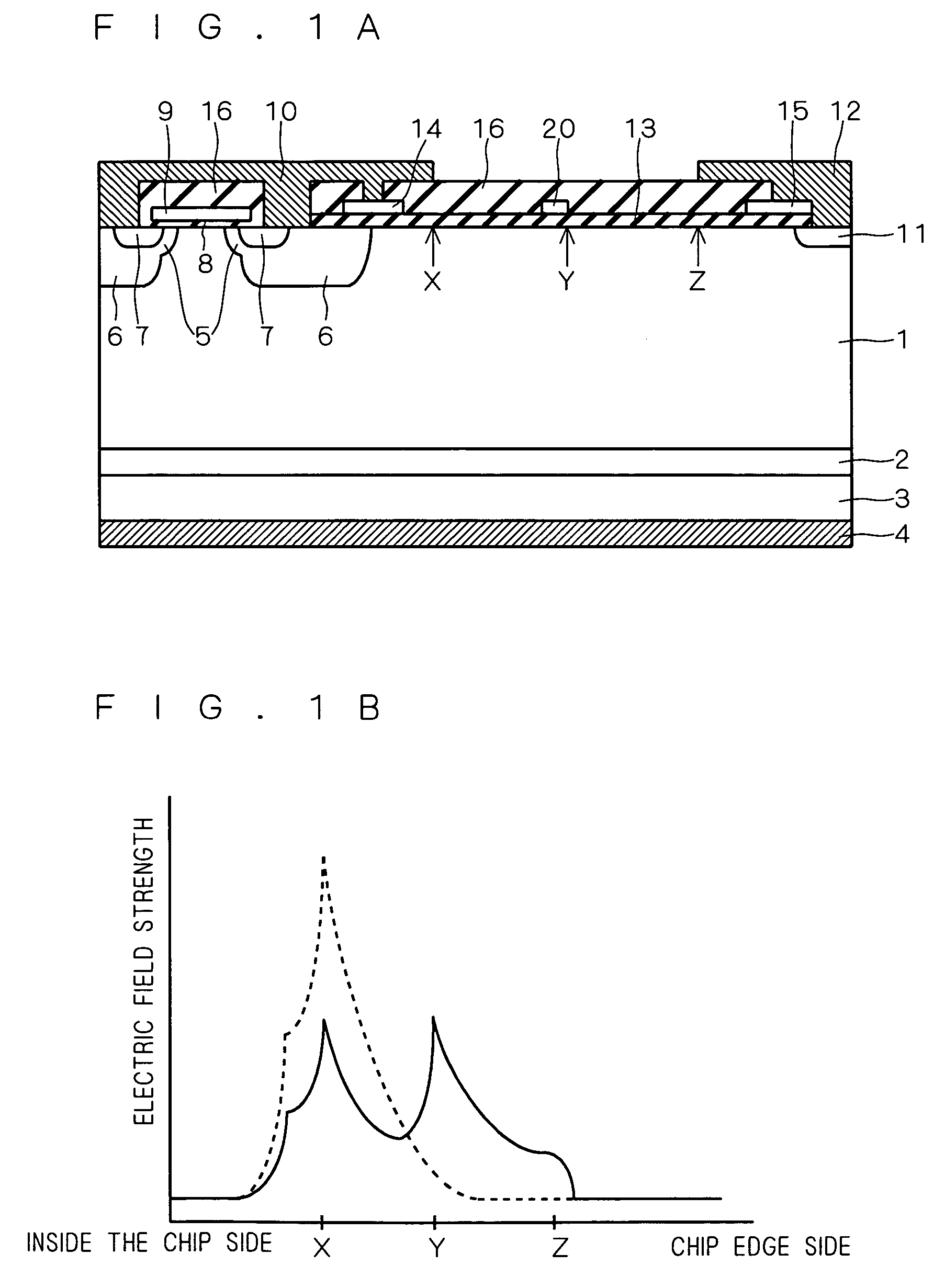
[0042]FIG. 1A illustrates the configuration of a semiconductor device according to a first preferred embodiment of this invention, which is a peripheral portion of a vertical IGBT chip. The left side portion of FIG. 1A is a region where an IGBT is formed as a semiconductor element for performing current switching, a cell portion of the IGBT. This portion is configured in a similar fashion as a typical IGBT. That is, on the under surface side of an n− drift layer 1, a p+ collector region 3 is formed via an n+ buffer layer 2 having lower resistance than the n− drift layer 1. A collector electrode 4 is provided on the under surface of the p+ collector region 3. In a surface layer on the top surface side of the n− drift layer 1, a p base region 5 is formed and, in order to prevent latchup of a parasitic thyristor, a p+ isolation well 6 is formed to overlap part of the p base region 5, the p+ isolation well 6 being of higher concentration and diffused deeper than the p base region 5. An ...

second preferred embodiment

[0060]FIG. 5 illustrates the configuration of a semiconductor device according to a second preferred embodiment of this invention, which is different from that shown in FIG. 1A in that a gate wiring 19 is connected to the field plate 14 on the low voltage side. Although not shown, the gate wiring 19 is electrically connected to the gate electrode 9. Namely, the field plate 14 and the gate electrode 9 are equal in potential. In FIG. 5, elements identical to those in FIG. 1A are denoted by like reference numbers, and descriptions thereof will thus be omitted. In this example, the outermost electrode (second electrode) on the substrate in the IGBT cell is the gate wiring 19.

[0061]Again in the FIG. 5 semiconductor device, there is provided the intermediate potential electrode 20 between the field plates 14 and 15 on the field oxide film 13. The electrode 20 is supplied with a lower intermediate potential than the silicon substrate surface therebelow from the intermediate potential apply...

third preferred embodiment

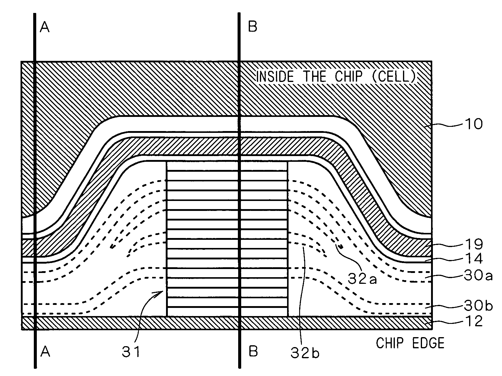
[0072]In a third preferred embodiment of this invention, a plurality of intermediate potential electrodes are provided on the chip peripheral portion. For instance, FIG. 9A illustrates the semiconductor device according to the first preferred embodiment including two intermediate potential electrodes 20a and 20b. The other components in FIG. 9A are identical to those in FIG. 1A, and detailed descriptions of FIG. 9A will thus be omitted.

[0073]When, with the potential at the collector electrode 4 (potential at the channel stopper electrode 12) being higher than the emitter electrode 10, the electrodes 20a and 20b are set to have a lower potential than the silicon substrate surface therebelow, a depletion layer extends easily in the n− drift layer 1 in the chip peripheral portion below the respective electrodes 20a and 20b. Conversely, when the electrodes 20a and 20b are set to have a higher potential than the silicon substrate surface therebelow, extension of a depletion layer is supp...


PUM


Abstract

In a peripheral portion of an IGBT chip, an intermediate potential electrode (20) is provided between a field plate (14) and a field plate (15) on a field oxide film (13), to surround an IGBT cell. The intermediate potential electrode (20) is supplied with a prescribed intermediate potential between the potentials at an emitter electrode (10) and a channel stopper electrode (12) from intermediate potential applying means that is formed locally in a partial region on the chip peripheral portion.

Description

BACKGROUND OF THE INVENTION[0001]1. Field of the Invention[0002]This invention relates to semiconductor devices, and in particular to techniques for stabilizing and enhancing breakdown voltage of semiconductor devices.[0003]2. Description of the Background Art[0004]It is generally required that power semiconductor device have high capability of holding breakdown voltage, namely, stability improvements in and enhancements of breakdown voltage are desired. Techniques known to accomplish this objective include a field plate, a guard ring, and a structure combining those elements (e.g. Japanese Patent Application Laid-Open No. 2003-188381). In another technique, diodes that are connected back-to-back with one another (back-to-back diode) are disposed between the gate and collector of an IGBT (insulated gate bipolar transistor) to thereby prevent an overvoltage from being applied between the collector and emitter (e.g. Japanese Patent No. 3191747 (2001)). Also known are a semiconductor d...

Claims


Application Information

Patent Timeline
Patent Type & Authority Patents(United States)
IPC IPC(8): H01L29/74H01L21/331H01L21/328H01L29/06H01L29/40H01L29/739H01L29/78
CPCH01L29/0696H01L29/405H01L29/66333H01L29/7395H01L2924/0002H01L2924/00H01L21/18H01L29/70H01L29/73
Inventor TAKAHASHI, TETSUO
Owner MITSUBISHI ELECTRIC CORP
Why Eureka
Try Eureka