
Method for using pulse compression in weather radar

a weather radar and pulse compression technology, applied in the field of weather radar signal processing, can solve the problems of preventing operationally realizing a commercial system, affecting the operation of weather radar, and competing frequency allocations, and achieves the effects of high sensitivity, short pulse range resolution, and greater sensitivity of long pulses

Active Publication Date: 2009-09-01
VAISALA
View PDF18 Cites 16 Cited by
  • Summary
  • Abstract
  • Description
  • Claims
  • Application Information

AI Technical Summary

Benefits of technology

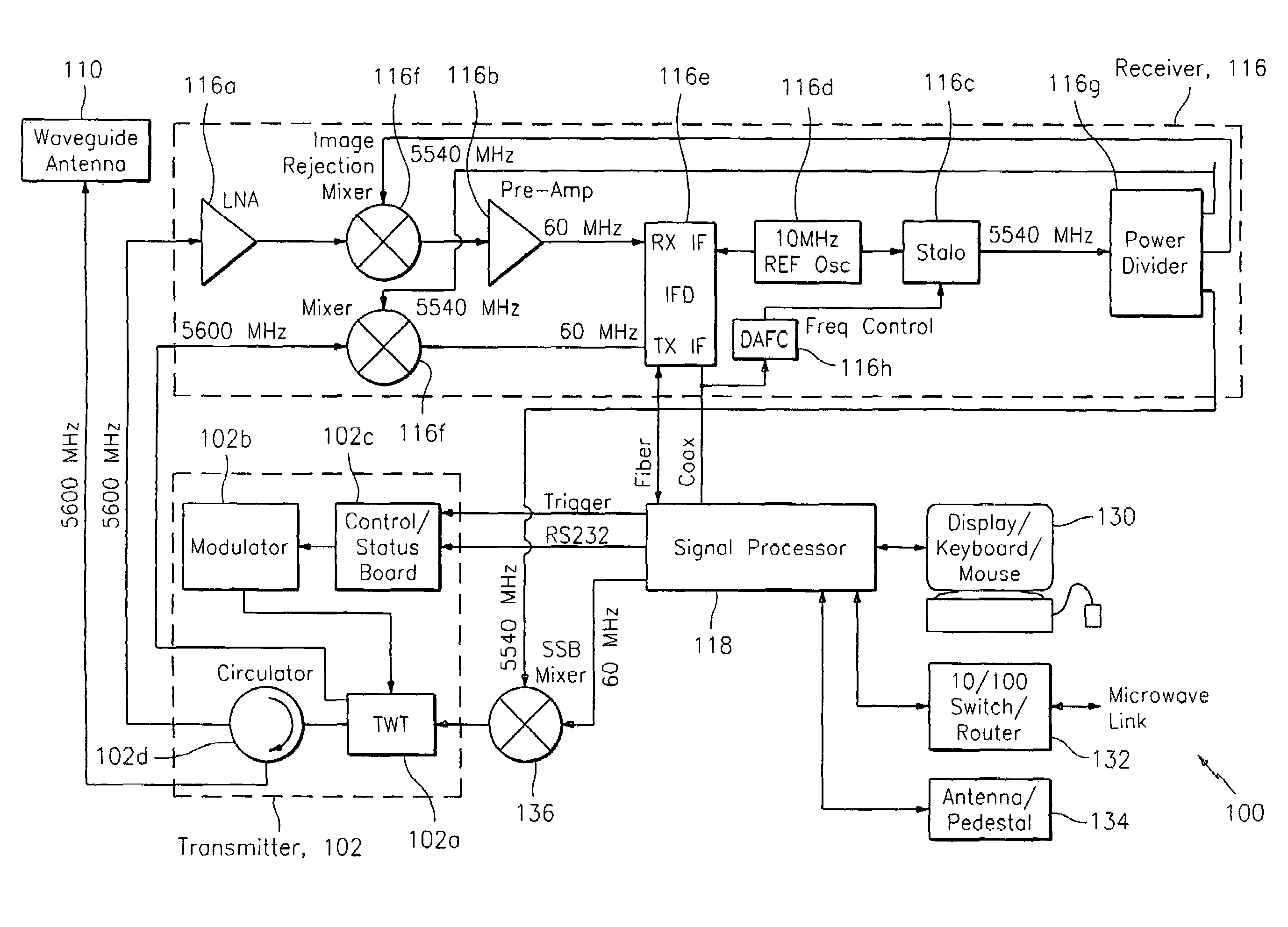
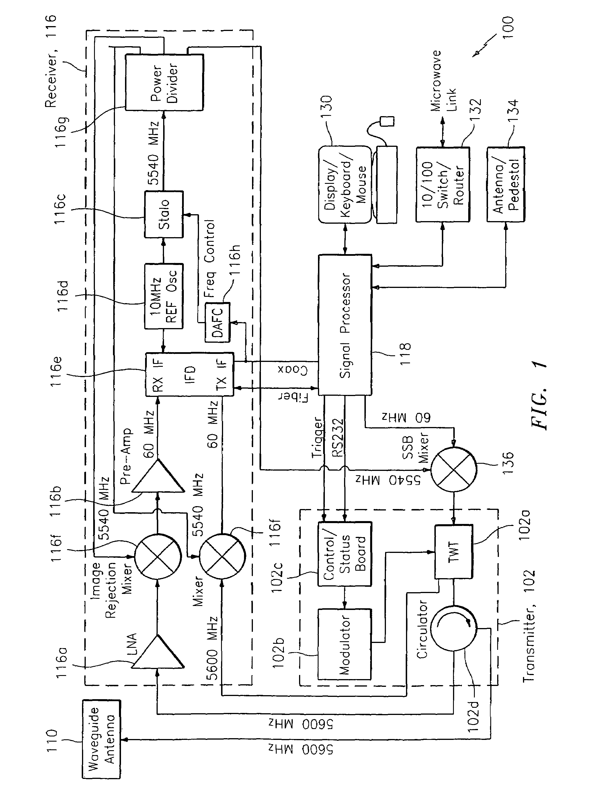
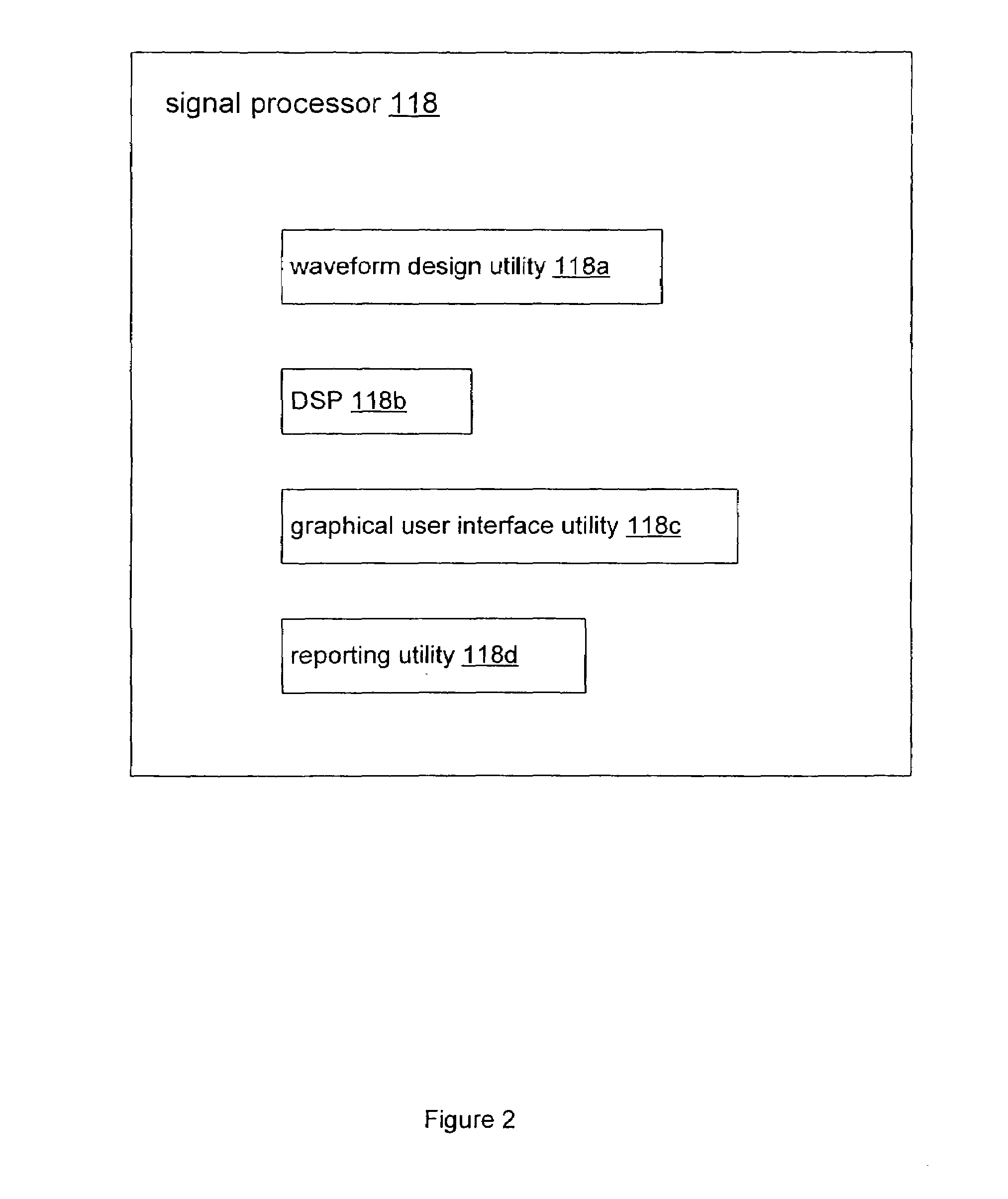
The patent text describes a method and system for improving the range resolution and sensitivity of radar by using pulse compression. The system achieves fine range resolution and low range time sidelobes while suppressing the effects of Doppler tolerance. The method includes generating long pulses with amplitude shaping and frequency modulation, using a mismatched windowed filter for pulse compression, and employing a weighted window function in the digital receiver. The system includes an antenna, transmitter, signal processor, and receiver connected through a waveform design utility. The technical effects of the invention include improved radar imaging and detection of weather phenomena.

Problems solved by technology

The modern explosion in wireless communication such as cell phones, wireless networks, and other broadcasts has created competition for frequency allocations and the potential for interference.
Historically, in the scope of meteorological radar, systems have been demonstrated that utilize pulse compression techniques, but such systems produced poor results.
The constraints of technology and / or economics have further prevented operationally realizing a commercial system.
Specifically, in the past, systems employing pulse compression techniques have shown poor results in obtaining ISL values sufficiently suppressed for practical use in meteorological radar over the range of target Doppler velocities expected to be measured by meteorological radar.
The result of these past implementations was high ISL values that blurred the meteorological images.
Thus, false readings, irresolvable echoes, breakthrough of ground clutter and other image contaminants rendered such techniques as poor options.

Method used


Image

  • Method for using pulse compression in weather radar
  • Method for using pulse compression in weather radar
  • Method for using pulse compression in weather radar

Examples


Embodiment Construction

[0024]The present invention overcomes many of the prior art problems associated with radar performance when using long compressed pulses, especially with meteorological radar. The advantages, and other features of the systems and methods disclosed herein, will become more readily apparent to those having ordinary skill in the art from the following detailed description of certain preferred embodiments taken in conjunction with the drawings which set forth representative embodiments of the present invention and wherein like reference numerals identify similar structural elements.

[0025]Unless otherwise specified, the illustrated embodiments can be understood as providing exemplary features of varying detail of certain embodiments, and therefore, unless otherwise specified, features, components, modules, elements, and / or aspects of the illustrations can be otherwise combined, interconnected, sequenced, separated, interchanged, positioned, and / or rearranged without materially departing ...


PUM


Abstract

A system and method for processing data related to weather phenomena in a meteorological radar system. The method includes receiving an echo signal generated by transmitting a long pulse and employing a mismatched windowed filter on the echo signal such that the echo signal is compressed in time to achieve fine range resolution without substantially degrading sensitivity and while achieving low range time side lobes for Doppler velocities expected to be measured by the meteorological radar system.

Description

CROSS-REFERENCE TO RELATED APPLICATION[0001]This application claims the benefit of Provisional Application Ser. No. 60 / 711,619 filed on Aug. 26, 2005, which is incorporated herein by reference.BACKGROUND OF THE INVENTION[0002]1. Field of the Invention[0003]The subject disclosure relates to methods and systems for weather radar signal processing, and more particularly to improved methods and systems for high sensitivity, fine range resolution and adequate suppression of Integrated Side Lobe (ISL) and Peak Side Lobe (PSL) in meteorological radar imagery.[0004]2. Background of the Related Art[0005]The modern explosion in wireless communication such as cell phones, wireless networks, and other broadcasts has created competition for frequency allocations and the potential for interference. Avoidance of interference from one system to another has created tight tolerances and a need to stay within an allocated range. As a result, longstanding applications like meteorological radar are bein...

Claims


Application Information

Patent Timeline
Patent Type & Authority Patents(United States)
IPC IPC(8): G01S13/00G01S13/04
CPCG01S7/282G01S13/951G01S13/582G01S13/282Y02A90/10
Inventor O'HORA, FRITZPASSARELLI, JR., RICHARD E.SIGGIA, ALAN D.VENKATACHALAM, CHANDRASEKARANBHARADWAJ, NITIN
Owner VAISALA
Learn More