
Waveguides for ultra-long range surface plasmon-polariton propagation

a waveguide and ultra-long-range technology, applied in the direction of optical waveguide light guide, optical element, instrument, etc., can solve the problems of metal film loss of metallic properties, metal film thickness less than 15 nm, and the propagation range provided by the conventional structure is not as great as desired for many applications

Inactive Publication Date: 2009-09-01
UNIVERSITY OF ALABAMA
View PDF30 Cites 31 Cited by
  • Summary
  • Abstract
  • Description
  • Claims
  • Application Information

AI Technical Summary

Benefits of technology

The patent text describes a method for using surface plasmon-polariton waves in a waveguide structure to propagate over long distances. The method involves using thin metal films or finite width thin metal strips to generate two modes of surface plasmon-polariton waves that couple together to form a long range surface plasmon-polariton wave mode. This mode has a longer travel range than the plasmon-polariton mode along a single surface of the bulk metal. The text also describes various methods for analyzing and evaluating surface plasmon-polariton waves in waveguides. The technical effect of this patent is to provide a way to propagate plasmon waves over long distances using a thin metal film or finite width thin metal strips.

Problems solved by technology

Reducing the thickness of metal films to less than 15 nm is problematic because it is experimentally difficult to deposit homogeneous metal films having a thickness of about 15 nm or less since metals typically form nanoscale islands in the initial deposition process.
In addition, many metal films lose their metallic property when the thickness of metal films approaches to the atomic scale
The propagation range provided by the conventional structure is not as great as desired for many applications.

Method used


Image

  • Waveguides for ultra-long range surface plasmon-polariton propagation
  • Waveguides for ultra-long range surface plasmon-polariton propagation
  • Waveguides for ultra-long range surface plasmon-polariton propagation

Examples


Embodiment Construction

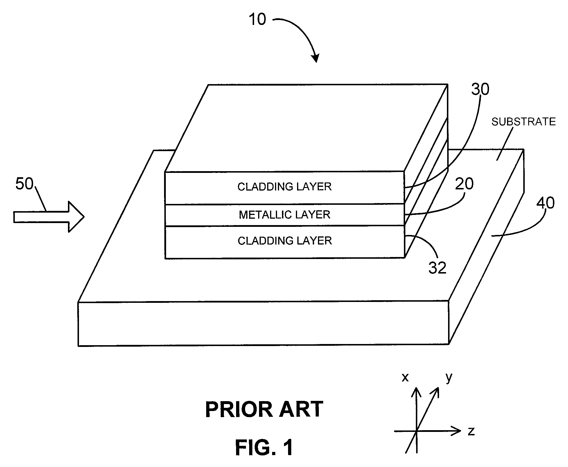
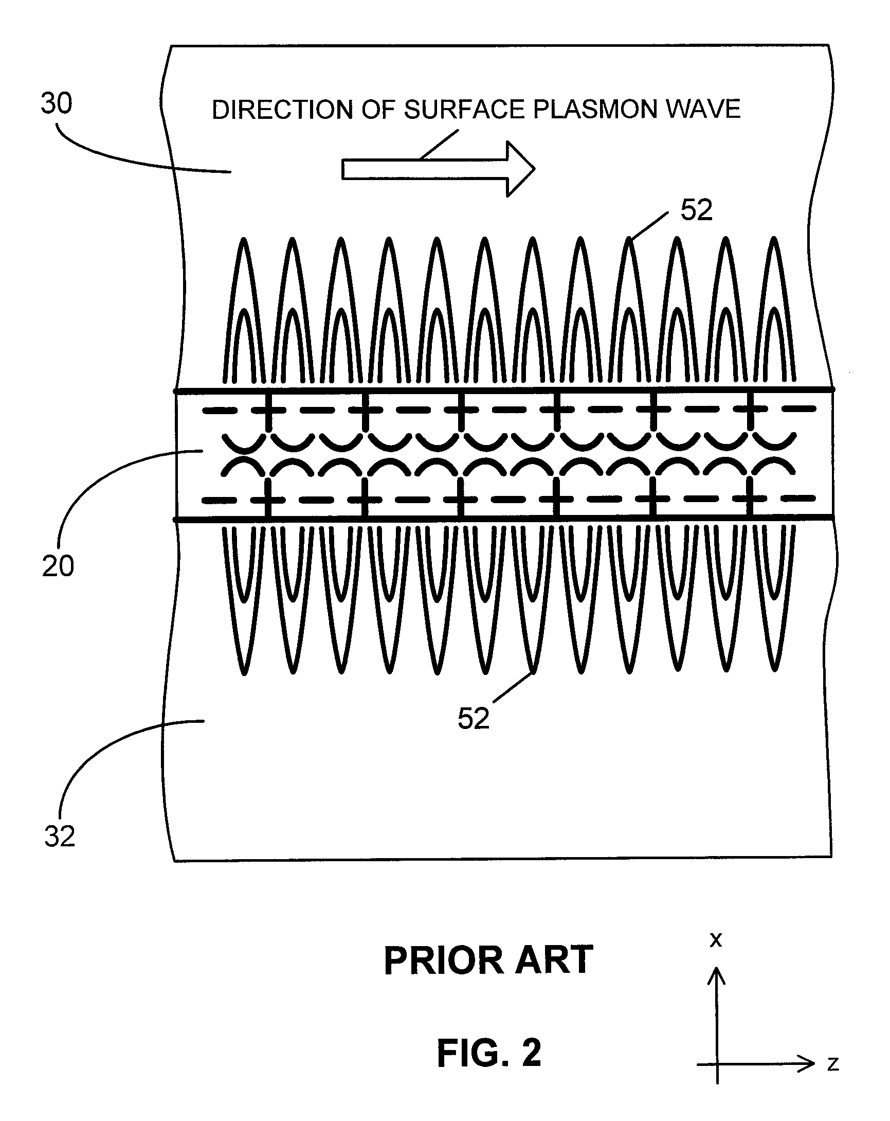
[0027]A conventional waveguide 10 for propagating a surface plasmon-polariton wave is depicted in FIG. 1. The conventional waveguide 10 guides a surface plasmon-polariton (SPP) wave in the z direction as shown. The long range surface plasmon-polariton mode of the conventional waveguide 10 has a propagation range of a few millimeters or less for surface plasmon-polariton waves that are induced by an excitation signal 50, such as a laser, at optical frequencies.

[0028]The conventional waveguide 10 comprises layers of material deposited on a substrate 40. The substrate 40 serves as a support structure for the other layers. A first homogeneous dielectric material is deposited on the substrate 40 and is referred to as a bottom homogeneous dielectric cladding layer 32. A metallic layer 20 is then deposited on the top surface of the bottom homogeneous dielectric layer 32. Another layer 30 of homogeneous dielectric material, referred to as the top homogeneous dielectric cladding layer 30, is...


PUM

PropertyMeasurementUnit
thicknessaaaaaaaaaa
thicknessaaaaaaaaaa
dielectric constantaaaaaaaaaa

Abstract

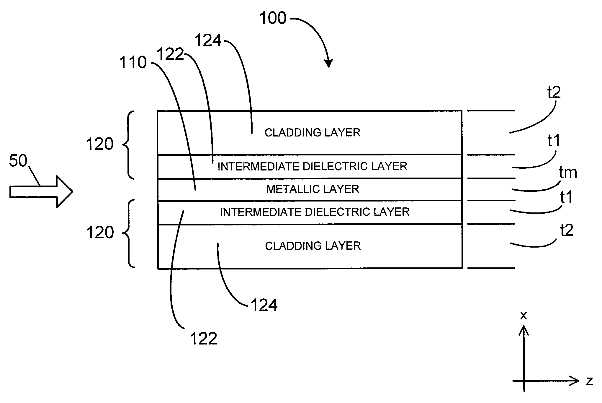
The disclosure relates to surface plasmon-polariton waveguides, which can guide ultra-long range surface plasmon-polariton waves. The attenuation of an ultra-long range surface plasmon-polariton waves is much lower than the attenuation of the conventional long range surface plasmon-polariton waves guided with the same kind of metal film or metal strip at the same plasmon-polariton frequency. An exemplary ultra-long range surface plasmon-polariton waveguide disclosed in this disclosure comprises a metal layer, such as a metal film or finite width metal strip, intermediate dielectric layers adjacent to the metal layer, and outer cladding dielectric material. The intermediate dielectric layers redistribute the electromagnetic energy distribution of the surface plasmon-polariton waves so that less of the energy propagates in the metal layer. Therefore, the attenuation of the surface plasmon-polariton wave is reduced. The propagation distance of the ultra-long range surface plasmon-polariton wave can be designed to a desired value by adjusting the thickness and the material property of the intermediate dielectric layers and other parameters related to the waveguide.

Description

CROSS REFERENCE TO RELATED APPLICATION[0001]This document claims priority to U.S. Provisional Application No. 60 / 865,316 entitled “Systems and Methods Using Ultra-Long Range Surface Plasmon Waves in Finite Width Metal Strips,” and filed on Nov. 10, 2006, which is incorporated herein by reference.RELATED ART[0002]Surface plasmons are free electron density oscillations on the surface of metals in dielectric media. The propagation of a surface plasmon couples with an electromagnetic wave along the boundary. The coupled state between the surface plasmon and the surface electromagnetic wave is referred as the surface plasmon-polariton (SPP). The electromagnetic field of the electromagnetic wave is a transverse magnetic (TM) field located near the surface of the metal. The condition for supporting a surface plasmon-polariton wave is that the two materials must have dielectric constants of opposite signs, such as, for example, a metal and a dielectric material. For example, when a boundary...

Claims


Application Information

Patent Timeline
Patent Type & Authority Patents(United States)
IPC IPC(8): G02B6/10G02F1/35
CPCG02B6/1226B82Y20/00
Inventor GUO, JUNPENG
Owner UNIVERSITY OF ALABAMA
Learn More