Multi-output power supply apparatus

a power supply apparatus and multi-output technology, applied in the direction of electric variable regulation, process and machine control, instruments, etc., can solve the problems of insufficient output supply, breakdown voltage may be exceeded, insufficient output supply, etc., and achieve the effect of wide input voltage rang

Active Publication Date: 2009-09-08
PANASONIC SEMICON SOLUTIONS CO LTD
View PDF7 Cites 5 Cited by
  • Summary
  • Abstract
  • Description
  • Claims
  • Application Information

AI Technical Summary

Benefits of technology

[0012]The present invention is intended to solve the problems with the conventional art. An object of the present invention is to provide an efficient multi-output power supply apparatus that enables a reduction in the on voltage of the main switch in the step-down power supply circuit or the like over a wide input range from a low input to a high input.
[0013]To accomplish the object, the present invention provides a multi-output power supply apparatus including a first power supply circuit that increases an input voltage supplied by an input power source to output a first output voltage, and a second power supply circuit that outputs a second output voltage obtained from the input voltage via a main switch circuit connected to the input power source, the main switch circuit in the second power supply circuit having a parallel configuration including a first switch element that is turned on by pulling a potential of a control terminal to a lower level and a second switch element that is turned on by pulling a potential of a control terminal to a higher level, wherein a source of a voltage applied to the control terminal of the second switch element is the first output voltage from the first power supply circuit. This configuration allows the first switch element to reduce an on voltage when the input voltage is high, while allowing the second switch element to reduce an on voltage when the input voltage is low, thus enabling the second power supply circuit to operate efficiently over an entire input voltage range.
[0015]Furthermore, the first and second switch elements included in the parallel configuration of the main switch circuit are a PMOS transistor and an NMOS transistor, respectively, and transistor sizes of the first and second switch elements are set so that an on resistance of the first switch element offered at a maximum input voltage is substantially equal to an on resistance of the second switch element offered at a minimum input voltage. This configuration makes it possible to inhibit a variation in the parallel on resistances of the first and second switch elements depending on the input voltage.
[0016]The multi-output power supply apparatus in accordance with the present invention includes a step-up power supply circuit and has thus an advantage that the apparatus makes it possible to construct a step-down power supply circuit and an inversion power supply circuit which operate efficiently over a wide input voltage range. The multi-output power supply apparatus in accordance with the present invention is therefore useful as a multi-output power supply.

Problems solved by technology

Thus, when the input voltage Vi is low, for example, 1.5 to 1.8 V as described above, the main switch 61 in the step-down power supply circuit 60 has an increased on voltage, resulting in insufficient output supply.
This may disadvantageously result in insufficient output supply.
Thus, disadvantageously, the breakdown voltage may be exceeded when the input voltage is high.

Method used


Image

  • Multi-output power supply apparatus
  • Multi-output power supply apparatus
  • Multi-output power supply apparatus

Examples


embodiment 1

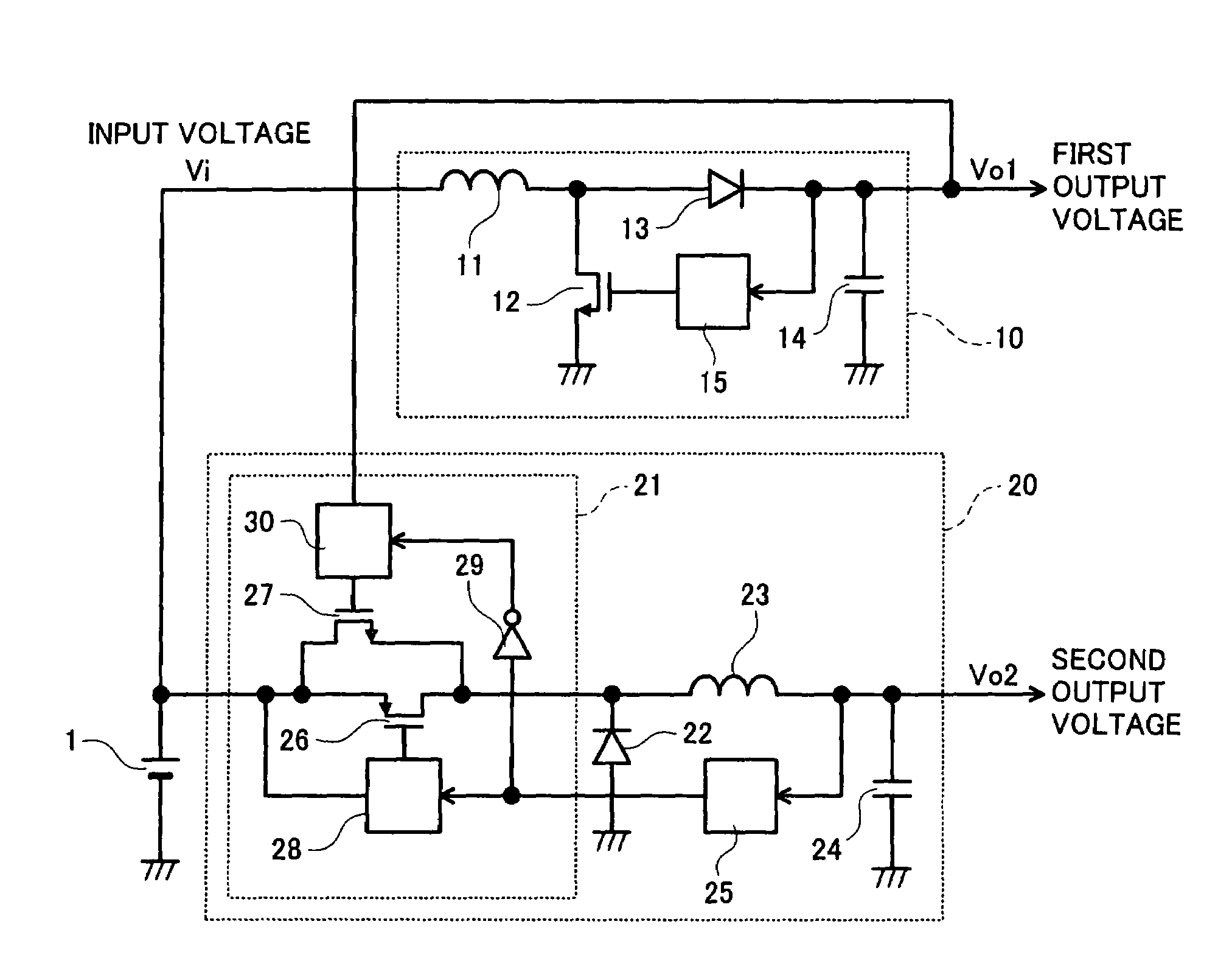
[0024]FIG. 1 is a circuit configuration diagram showing a multi-output power supply apparatus in accordance with Embodiment 1 of the present invention. Here, the same reference numerals as those in FIG. 5 showing the conventional example are used to denote components of Embodiment 1 which correspond to those described with reference to FIG. 5 and which provide functions equivalent to those described with reference to FIG. 5.

[0025]As shown in FIG. 1, reference numeral 1 denotes an input power source such as a battery which provides an input voltage Vi. Reference numeral 10 denotes a step-up power supply circuit which is a first power supply circuit and which increases the input voltage Vi to output a first output voltage Vo1. The step-up power supply circuit 10 is composed of an inductor 11 connected to the input power source 1, which provides the input voltage Vi, a main switch 12 made of an NMOS transistor and connected to the other end of the inductor 11, a diode 13 and an output ...

embodiment 2

[0037]FIG. 4 is a circuit configuration diagram of a multi-output power supply apparatus in accordance with Embodiment 2 of the present invention. In Embodiment 2, the second power supply circuit configured as the step-down power supply circuit 20 in accordance with Embodiment 1, described above, is constructed using a third power supply circuit (inversion power supply circuit 40). As shown in FIG. 4, the inversion power supply circuit 40, the third power supply circuit, inverts and increases or reduces the input voltage Vi to output a third output voltage Vo3.

[0038]The inversion power supply circuit 40 is composed of a main switch circuit 41 having an input terminal connected to the input power source 1, an inductor 42 connected to an output terminal of the main switch circuit 41, a diode 43 having a cathode connected to the connection point between the output terminal of the main switch circuit 41 and the inductor 42, an output capacitor 44 connected to an anode of the diode 43 fo...


PUM


Abstract

The present invention provides an efficient multi-output power supply apparatus that enables a reduction in the on voltage of a main switch in a step-down power supply circuit or the like over a wide input range from a low input to a high input. The power supply apparatus includes a first power supply circuit that increases an input voltage from an input power source to output a first output voltage Vo1, and a second power supply circuit that outputs a second output voltage Vo2 obtained from the input voltage via a main switch circuit connected to the input power source. The main switch circuit having a first switch element that is a PMOS transistor and a second switch element that is an NMOS transistor connected to each other in parallel. The first output voltage Vo1 is applied to a gate of the second switch element.

Description

FIELD OF THE INVENTION[0001]The present invention relates to a multi-output power supply apparatus including a step-up power supply circuit and one of a step-down power supply circuit and an inversion power supply circuit.BACKGROUND OF THE INVENTION[0002]Electronic equipment recently used as portable equipment uses batteries as power source and has a multi-output power supply apparatus made of a plurality of power supply circuits in order to convert the voltage of the battery into desired power supply voltages for the various electronic circuits in the equipment. The battery voltage tends to be used down to a lower level in order to allow the equipment to operate longer. For example, input specifications for two size AA batteries are such that an initial input voltage is 3.4 V and a lower limit input voltage is 1.5 to 1.8 V. On the other hand, various power supply voltages are demanded. For example, for digital still cameras, 5 V is required for lens driving, and 1.2 V is required f...

Claims


Application Information

Patent Timeline
Patent Type & Authority Patents(United States)
IPC IPC(8): H04B15/00G05F1/577H03L5/00
CPCH02J1/08H02J1/108H02J2001/008H02J1/082
Inventor MORITA, JUNICHIISHII, TAKUYAMOTOMORI, MIKIO
Owner PANASONIC SEMICON SOLUTIONS CO LTD
Why Eureka
Try Eureka