Method and apparatus for motor control

a technology of permanent magnet or permanent magnet motor control, applied in the direction of motor/generator/converter stopper, dynamo-electric converter control, transportation and packaging, etc., can solve the problem that existing pm or ipm motor control methods and apparatus, especially in electric or hybrid vehicle applications, may perform poorly when the dc bus voltage varies, and existing pm or ipm motor control systems and methods are typically insufficient compensation

Inactive Publication Date: 2009-09-08
CONTINENTAL AUTOMOTIVE SYST INC
View PDF20 Cites 91 Cited by
  • Summary
  • Abstract
  • Description
  • Claims
  • Application Information

AI Technical Summary

Problems solved by technology

As a result, rapid changes in vehicle load may cause large fluctuations in the DC bus voltage.
Existing PM or IPM motor control methods and apparatus, particularly in electric or hybrid vehicle applications, may perform poorly when the DC bus voltage varies.
Rapid fluctuation of the DC bus voltage, for example due to rapidly changing power demands, exacerbates this problem, and existing PM or IPM motor control systems and methods are typically unable to adequately compensate.
Furthermore, due to the multiple optimal curves and boundaries imposed on the motor current commands, simple regulators that can control the motor torque output precisely and quickly in the high speed and / or the field weakening operating regions do not appear to be available.

Method used


Image

  • Method and apparatus for motor control
  • Method and apparatus for motor control
  • Method and apparatus for motor control

Examples


Embodiment Construction

[0021]In the following description, certain specific details are set forth in order to provide a thorough understanding of various embodiments. However, one skilled in the art will understand that the embodiments may be practiced without these details. In other instances, well-known structures associated with PM motors, controllers, microprocessors, and various electrical components have not been shown or described in detail to avoid unnecessarily obscuring descriptions of the embodiments.

[0022]Unless the context requires otherwise, throughout this specification and claims which follow, the word “comprise” and variations thereof, such as, “comprises” and “comprising” are to be construed in an open, inclusive sense, that is as “including, but not limited to.”

[0023]The headings provided herein are for convenience only and do not interpret the scope or meaning of the claimed invention.

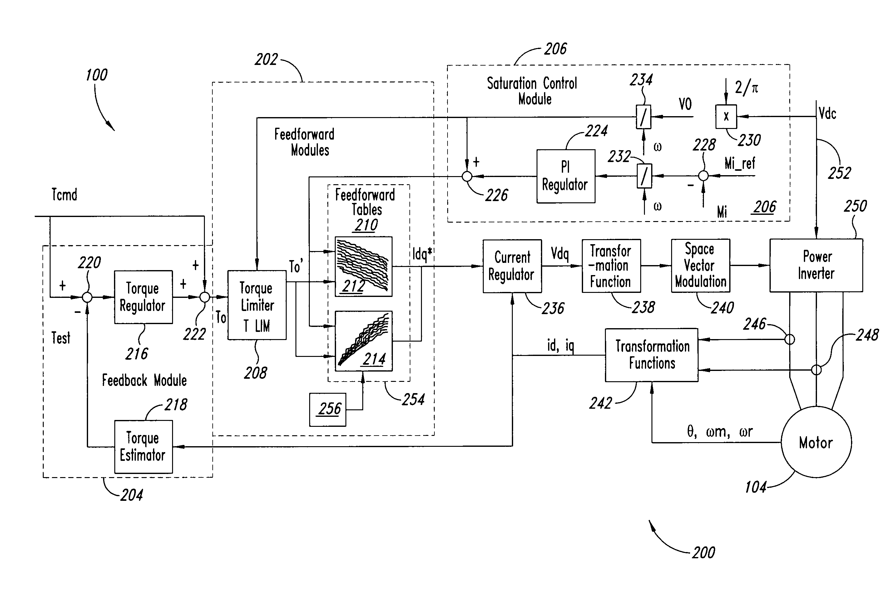
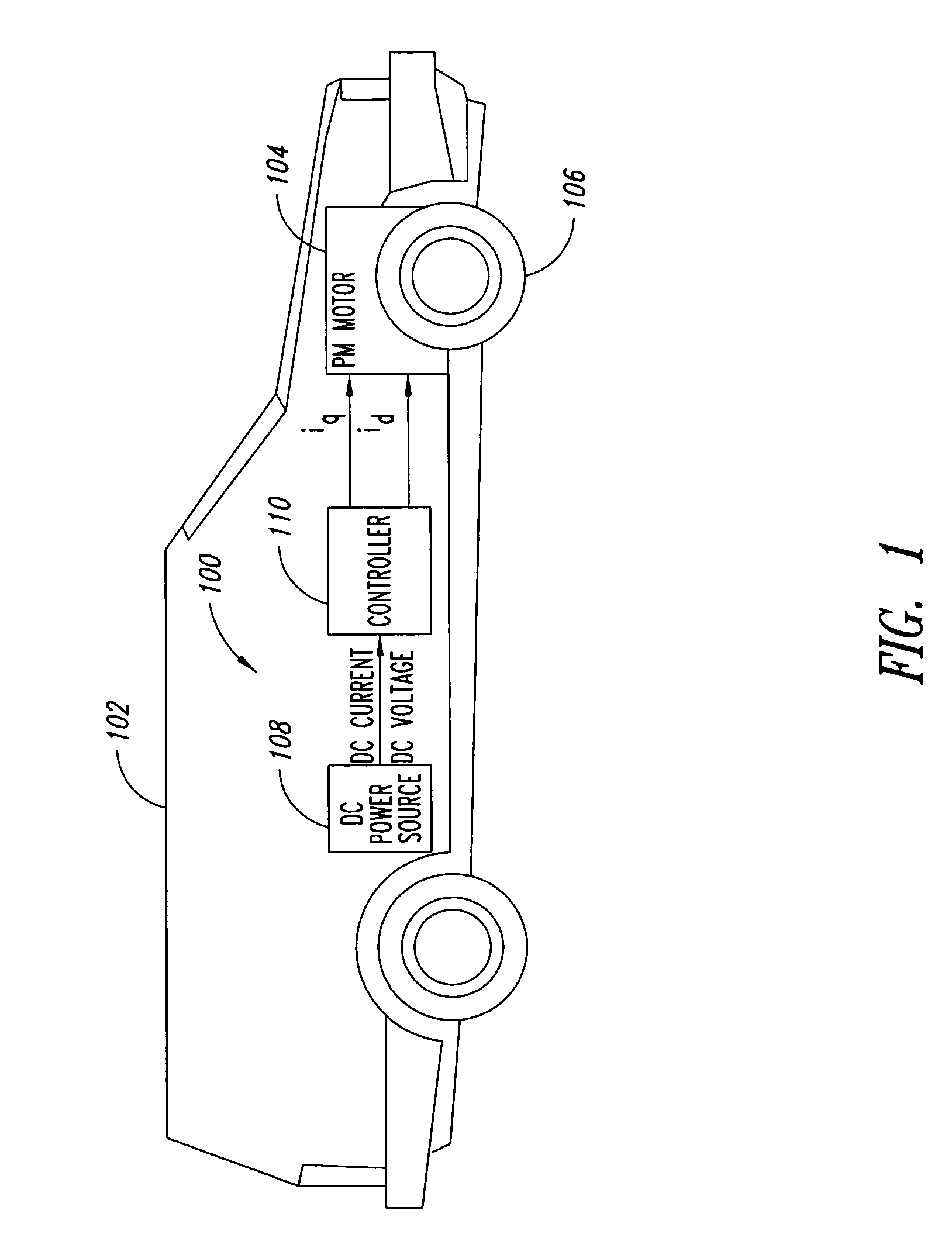
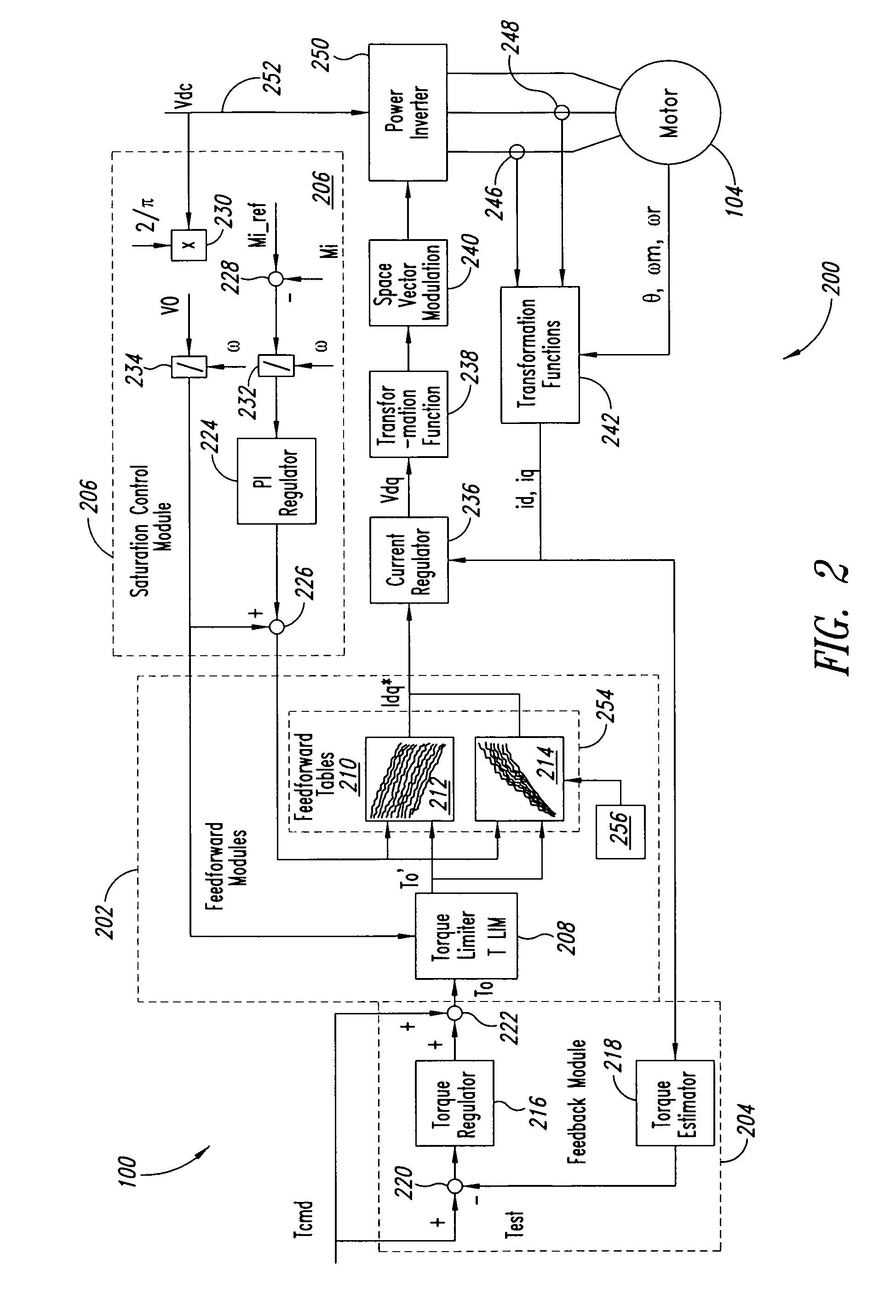
[0024]FIG. 1 is a schematic diagram of a torque feedforward compensation system 100 implemented in an ...


PUM


Abstract

A system and method for controlling a permanent magnet motor are disclosed. Briefly described, one embodiment receives a torque command and a flux command; receives information corresponding to a direct current (DC) bus voltage and a motor speed; computationally determines feedforward direct-axis current information and feedforward quadrature-axis current information from a plurality of parameters associated with the permanent magnet motor; determines a current signal (idq*) based upon at least the requested torque command, the flux command, the DC bus voltage, the motor speed, the feedforward direct-axis current information, and the feedforward quadrature-axis current information; and controls a power inverter that converts DC power into alternating current (AC) power that is supplied to the permanent magnet motor, such that the permanent magnet motor is operated in accordance with the determined idq*.

Description

BACKGROUND[0001]1. Field[0002]The present disclosure generally relates to motor control, and more particularly relates to permanent magnet or interior permanent magnet motor control.[0003]2. Description of the Related Art[0004]The permanent magnet (PM) synchronous motor possesses many appealing characteristics for various applications, including pure-electric or hybrid-electric vehicles. The maximum input power of a vehicle is dictated, in part, by the size of the power sources (i.e., battery, fuel cell engine, supercapacitor, etc.). Direct current (DC) power is the product of the DC voltage and DC current. Quite often, the DC bus voltage varies with motor output power (i.e., Torque*Speed). As a result, rapid changes in vehicle load may cause large fluctuations in the DC bus voltage.[0005]Traction electric motors may be used to propel electric or hybrid vehicles. A traction electric motor drive is often required to perform over a wide operating range. Typically the operating range o...

Claims


Application Information

Patent Timeline
Patent Type & Authority Patents(United States)
IPC IPC(8): H02P27/04
CPCB60L15/025H02P23/004H02P21/0035Y02T10/643B60L2240/421B60L2240/423B60L2240/427B60L2240/429B60L2260/42H02P23/30H02P21/22Y02T10/64
Inventor CHENG, BINGTESCH, TOD R.
Owner CONTINENTAL AUTOMOTIVE SYST INC
Why Eureka
Try Eureka