Method of making a tubular

Inactive Publication Date: 2009-09-15
GARZA RAUL
View PDF6 Cites 19 Cited by
  • Summary
  • Abstract
  • Description
  • Claims
  • Application Information

AI Technical Summary

Problems solved by technology

Unfortunately, in the manufacturing of present tubular products or other related steel products, it is impossible to paint a barcode and numbers with paint that is able withstand the severe thermal shock at the heat treatment portion of the manufacturing processes.
This often de

Method used


Image

  • Method of making a tubular
  • Method of making a tubular
  • Method of making a tubular

Examples


Example

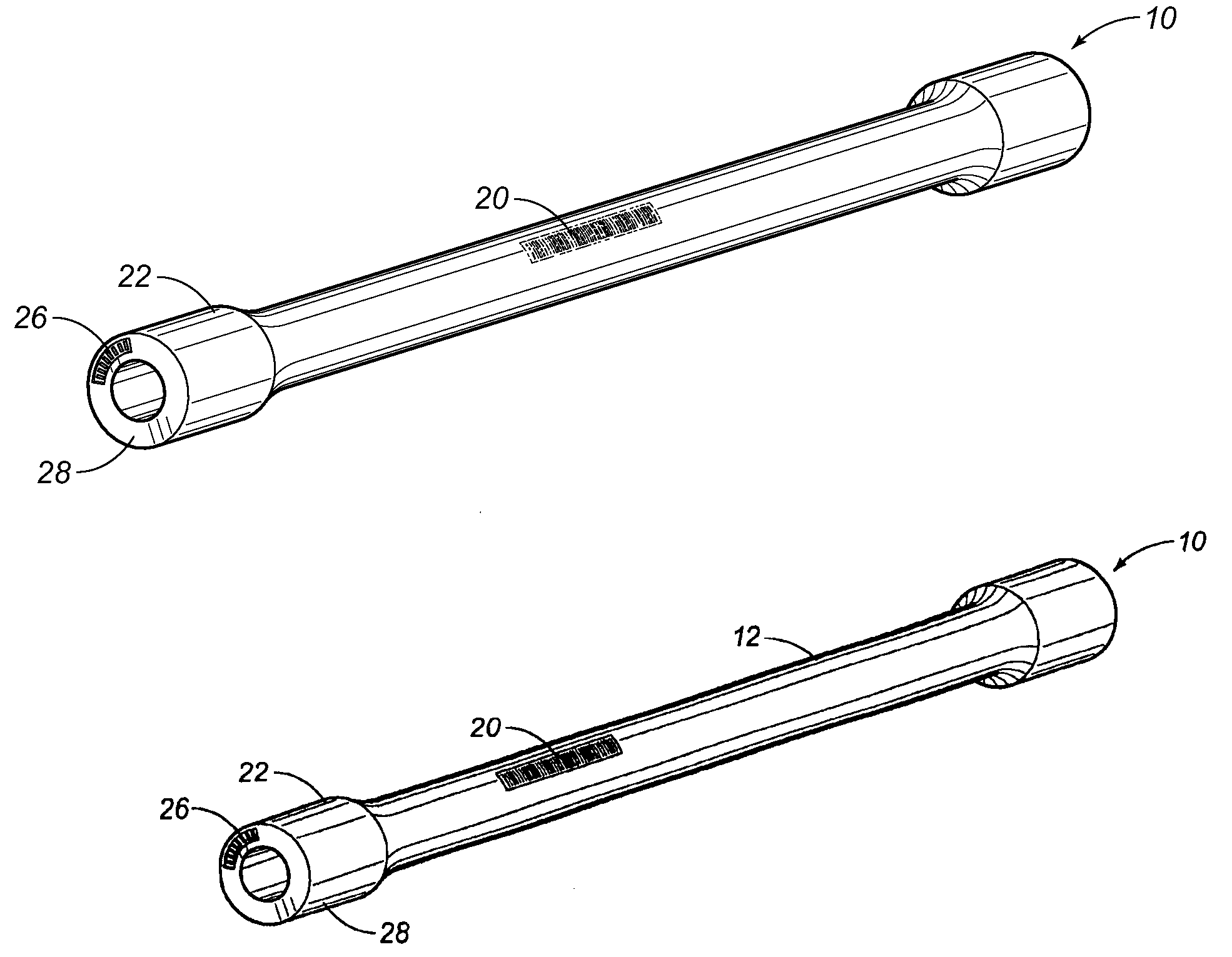
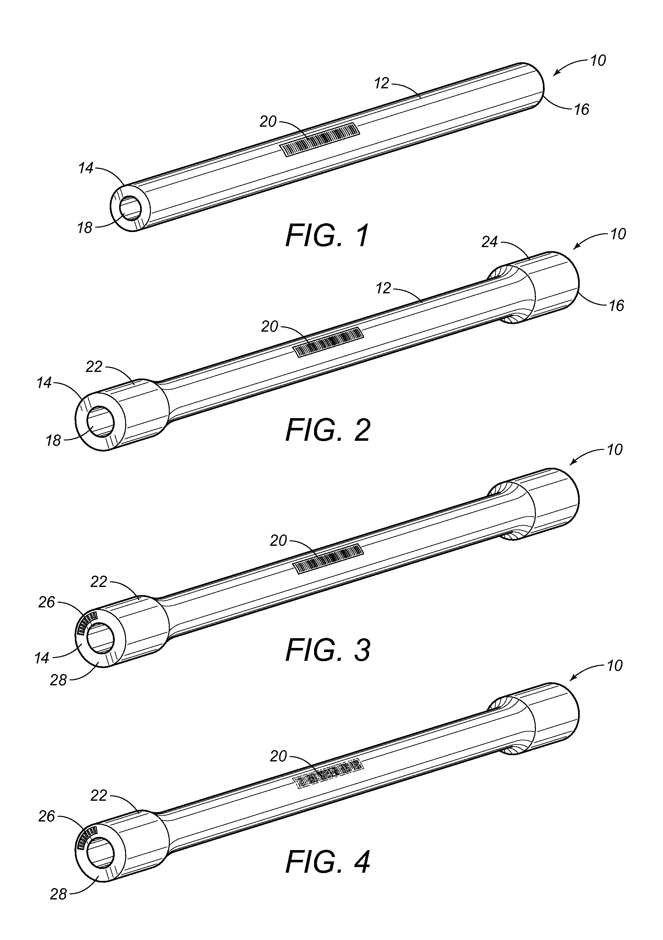
[0032]Referring to FIG. 1, there is shown the tubular 10. The identification indicia 20 is located generally centrally on the pipe 12 between the ends 14 and 16. This identification indicia 20 is a bar code which will contain information relating to the tubular 10. This information can be in the nature of heat numbers, lot, purchase order number, pipe description and pipe condition. The pipe description can be in the nature of describing the length of pipe 12, the diameter of pipe 12, the wall thickness of pipe 12 and the type of steel used for the pipe 12. Additionally, such identification indicia 20 can also be indicative of the manufacturer of the tubular 10, the location of the manufacturer, and other detailed information. The application of such the identification indicia 20 onto the outer diameter of the pipe 12 is presently carried out conventionally in manufacturing operations.

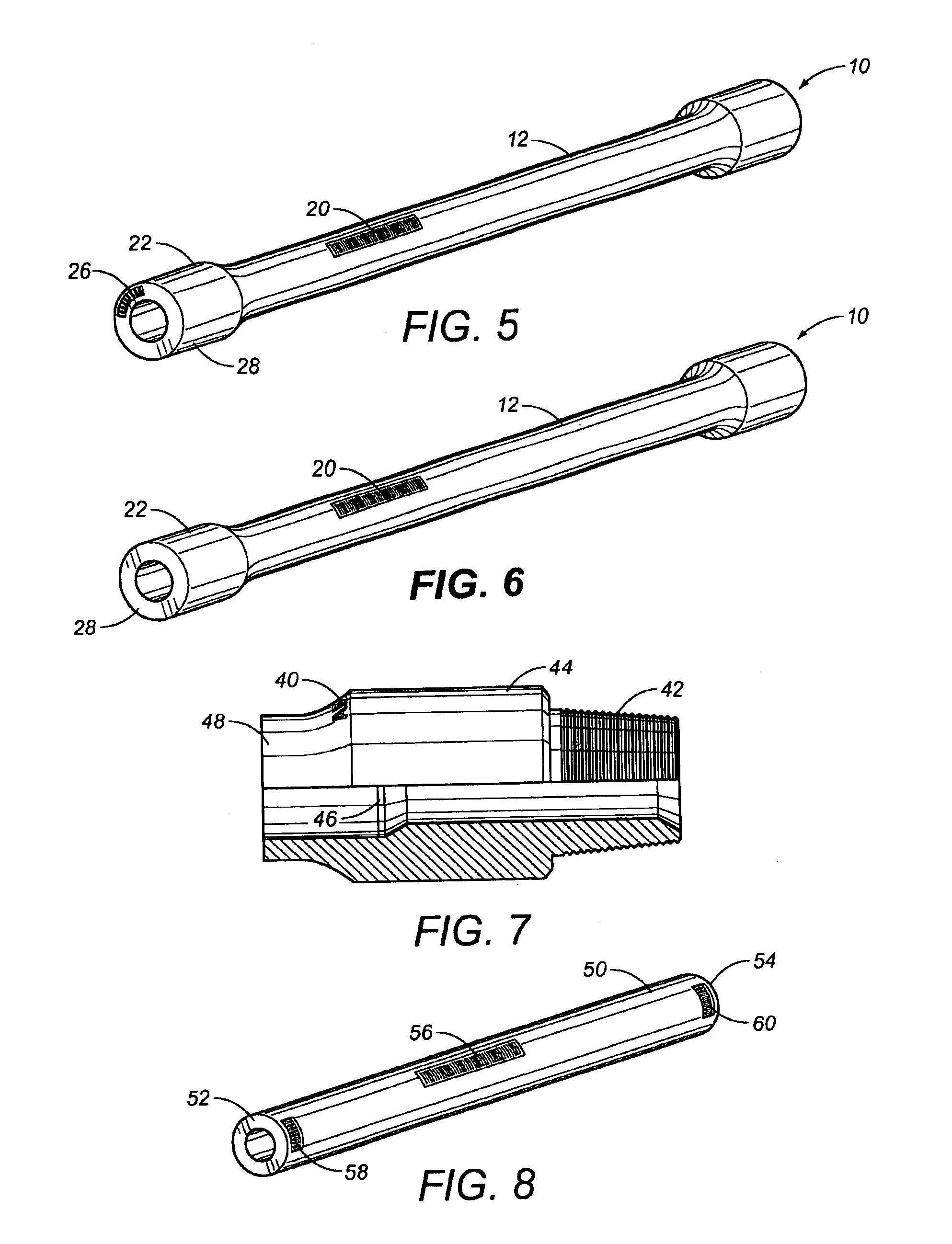
[0033]In FIG. 2, it can be seen that the tubular 10 has a first upset 22 that is formed adjacent to...


PUM

PropertyMeasurementUnit
Temperatureaaaaaaaaaa
Angleaaaaaaaaaa
Diameteraaaaaaaaaa

Abstract

A method of marking a tubular includes the steps of applying an identification indicia onto the outer diameter of the tubular, forming an indicator onto at least one of the ends of the tubular such that the indicator corresponds to information in the identification indicia, heat treating the tubular such that the identification indicia is diminished, and reapplying the identification indicia onto the outer diameter of the tubular based upon the indicator formed on the end of the tubular. The tubular has an upset formed on at least one end thereof. The end of the tubular is machined so as to remove the indicator therefrom after the identification information is reapplied to the outer diameter of the tubular.

Description

RELATED U.S. APPLICATIONS[0001]Not applicable.STATEMENT REGARDING FEDERALLY SPONSORED RESEARCH OR DEVELOPMENT[0002]Not applicable.REFERENCE TO MICROFICHE APPENDIX[0003]Not applicable.FIELD OF THE INVENTION[0004]The present invention relates to the forming and manufacturing of tubulars. More particularly, the present invention relates to the manufacturing of tubular products and tubulars having an upset formed on at least one end thereof. Furthermore, the present invention relates to techniques for marking such tubulars during the manufacturing process and during the forming of the upset of the tubular.BACKGROUND OF THE INVENTION[0005]Metal pipe, such as drill pipe, is normally assembled by joining adjacent lengths of drill pipe. The ends of the drill pipe are normally upset for welding to a threaded tool joint for connection of adjacent pipe lengths. The drill pipe lengths prior to forming of the upset ends and threads are of a constant wall thickness and have uniform inner and oute...

Claims


Application Information

Patent Timeline
IPC IPC(8): B21D3/00B21C37/00B21D41/00
CPCB21C51/00
Inventor GARZA, RAUL
Owner GARZA RAUL
Why Eureka
Try Eureka