
Anti-sulfur well mouth valve body welding repair method

A technology of welding repair and valve body, which is applied in the direction of welding medium, welding equipment, welding equipment, etc., can solve the problems of structural failure, welding joint joint strength, welding seam composition difficult to meet relevant requirements, and repair difficulty, etc., to achieve high load bearing ability, avoid repeated repair welding rework, and avoid softening problems

Active Publication Date: 2017-12-29
YANTAI JEREH PETROLEUM EQUIP & TECH
View PDF6 Cites 81 Cited by
  • Summary
  • Abstract
  • Description
  • Claims
  • Application Information

AI Technical Summary

Problems solved by technology

[0003] 1. During use, the flow channel holes and gasket grooves of wellhead valve bodies (including fracturing valves, flat valves, etc.) will be eroded and the seat mounting surface will often be scratched, resulting in failure of the entire structure problem, this type of valve body cannot continue to be used without repair
[0004] 2. In the process of processing, the size of the product is often out of tolerance due to problems such as knives, and there have been cases where the sealing surface was scratched during the test. If it is not repaired, it can only be scrapped.
[0005] Most of the above valve bodies have anti-sulfur composition and hardness requirements. The matrix is ​​4130 medium carbon alloy steel. The hardness of the heat-affected zone will exceed the anti-sulfur requirements after ordinary repair welding. Joint strength, weld composition, etc. are difficult to meet the relevant requirements, and the joint cannot achieve the expected repair purpose
And in most cases, the product has been processed to size, and it is necessary to consider the impact of welding deformation, undercut and other welding defects on the size of the product. It is difficult to repair and can only be scrapped, resulting in huge waste

Method used


Image

  • Anti-sulfur well mouth valve body welding repair method

Examples


Embodiment 1

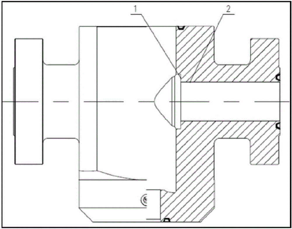
[0032] 1. Clean the product to be repaired, and process one damaged sealing surface, removing 1.5mm on one side;

[0033] 2. For the two eroded pits, it is necessary to polish and repair the welding pit and the surrounding 20-30mm surface to remove rust and oil stains, revealing the metallic luster, and clean the polished surface with absolute ethanol or acetone;

[0034] 3. The workpiece is preheated to 130°C as a whole before welding;

[0035] 4. Using Ar+CO 2 The mixed gas shielded welding fills the 2 pits and fills with 655MPa high-toughness welding wire. The chemical composition of the deposited metal is: C≤0.11%, Si 0.5%-0.9%, Mn 1.4%-1.8%, Cu ≤0.5%, Cr 0.20%~0.6%, Ti≤0.17%, S≤0.025%, P≤0.025%, the balance is Fe; the volume ratio of Ar and CO2 gas is 80%:20%, and the welding parameters are: filling The diameter of the welding wire is 1.2mm, the welding voltage is 22-26V, the welding current is 200-260A, and the flow rate of the shielding gas is 15-22L / min.

[0036] 5....


PUM

PropertyMeasurementUnit
Tensile strengthaaaaaaaaaa
Impact absorption energyaaaaaaaaaa
Hardnessaaaaaaaaaa

Abstract

The invention belongs to the welding industry, and particularly relates to an anti-sulfur well mouth valve body welding repair method, and in particular to a welding repair method of 4130 medium-carbon alloy steel in an anti-sulfur valve body with the hardness being 197 HBW -237 HBW. The anti-sulfur well mouth valve body welding repair method is characterized by comprising the following steps that a product to be repaired is cleaned to determine a damage position; a pit badly eroded needs to be polished; a workpiece is totally preheated to 130 DEG C before welding; filling of the pit is firstly achieved by adopting the argon tungsten-arc welding; then, the machined surface is subject to repair welding; the local or total heat treatment insulation is performed for 3 hours at 640 DEG C; in the welding repair method, preheating is performed to reach 130 DEG C before welding; the local or total heat treatment insulation is performed for 3 hours at 640 DEG C after welding; and the Ar+CO2 mixed gas arc welding is adopted in the method, and the method greatly increases the product utilization rate and improves the comprehensive efficiency.

Description

technical field [0001] The invention belongs to the welding industry, and specifically relates to a welding repair method for an anti-sulfur wellhead valve body, in particular to a welding repair method for a medium-carbon alloy steel with a hardness of 197--237 HBW 4130 for an anti-sulfur valve body . Background technique [0002] Many products of wellhead valve bodies (including fracturing valves, flat valves, etc.) will be applied to a medium-carbon alloy steel material with a hardness of 197-237 HBW 4130. These products will inevitably suffer from the following during processing, testing and use. The problem causes the structure to fail: [0003] 1. During use, the flow channel holes and gasket grooves of wellhead valve bodies (including fracturing valves, flat valves, etc.) will be eroded and the seat mounting surface will often be scratched, resulting in failure of the entire structure Problems, such valve bodies cannot continue to be used without repair. [0004] 2...

Claims


Application Information

Patent Timeline
IPC IPC(8): B23K9/167B23K9/235B23K35/30
CPCB23K9/167B23K9/235B23K35/3053
Inventor 孙建雄朱建邦
Owner YANTAI JEREH PETROLEUM EQUIP & TECH
Learn More