Method and apparatus for producing plasma

a plasma and plasma technology, applied in the field of plasma production, can solve the problems of high cost disadvantages of vacuum plasma chambers, and high cost of certain vacuum components, and achieve the effects of enhancing an electric field, low cost, and increasing the electric field

Inactive Publication Date: 2009-09-15
DUBLIN CITY UNIVERSITY
View PDF21 Cites 100 Cited by
  • Summary
  • Abstract
  • Description
  • Claims
  • Application Information

AI Technical Summary

Benefits of technology

[0008]Embodiments of the present invention provide a low cost and environmentally friendly method and apparatus for producing a plasma at atmospheric pressure. An illustrative embodiment of the invention produces plasma using a high frequency power source in communication with a waveguide. The illustrative embodiment enhances an electric field to produce plasma by using a plurality of particularly designed couplers configured with the waveguide. The couplers extend through the waveguide wall and include internal portions inside the waveguide. The internal portions are spaced according to half-wavelengths of a high frequency power source that provides power to the waveguide so that adjacent couplers are 180 degrees out of phase with each other. The couplers include external portions that can be spaced apart from external portions of adjacent couplers by a distance that is different from the spacing distance of the internal portions. The spacing of the external portions of adjacent couplers can be chosen to increases the electric field between them.
[0011]Embodiments of the present invention can be modified to use numerous types of high frequency power sources having a frequency range in excess of about 1 GHz. In an illustrative embodiment, the method employs a high frequency power source such as 2.45 GHz magnetron that is widely available and is commonly used in microwave ovens. A circulator and matched load prevents the magnetron from receiving reflected power. A directional coupler is used to measure forward and reflected power. Couplers are introduced into a waveguide section with the high amplitude standing waves wherein the internal portions of the couplers are arranged with ½ wavelength spacing and aligned with the large amplitude electric or magnetic fields, depending on nature of the internal component of the couplers. External portions of the couplers come into close proximity with adjacent couplers, so the field amplitude in the gaps between external portions is further enhanced.

Problems solved by technology

Vacuum chambers can be problematic and unduly expensive for use in certain applications.
Vacuum plasma chambers can be disadvantageous because certain vacuum components are expensive, cumbersome and require high maintenance.
These types of plasma generators tend to produce non-uniform plasma distributions, which are often referred to as filamentary discharges, in the chamber.
Such atmospheric pressure plasma generators have a tendency to damage surfaces of work-pieces.
For example, work-pieces in presently known atmospheric pressure plasma generators can be subject to arcing and / or levels of directional current which can cause heat damage to their surfaces.
These methods have been less than optimal because they consume excessive quantities of helium.
Like arcing, the localized high ion flux that occurs in plasma jet systems can damage a surface such of a work-piece.
The use of two power sources makes this type of plasma generator very expensive.

Method used


Image

  • Method and apparatus for producing plasma
  • Method and apparatus for producing plasma
  • Method and apparatus for producing plasma

Examples


Embodiment Construction

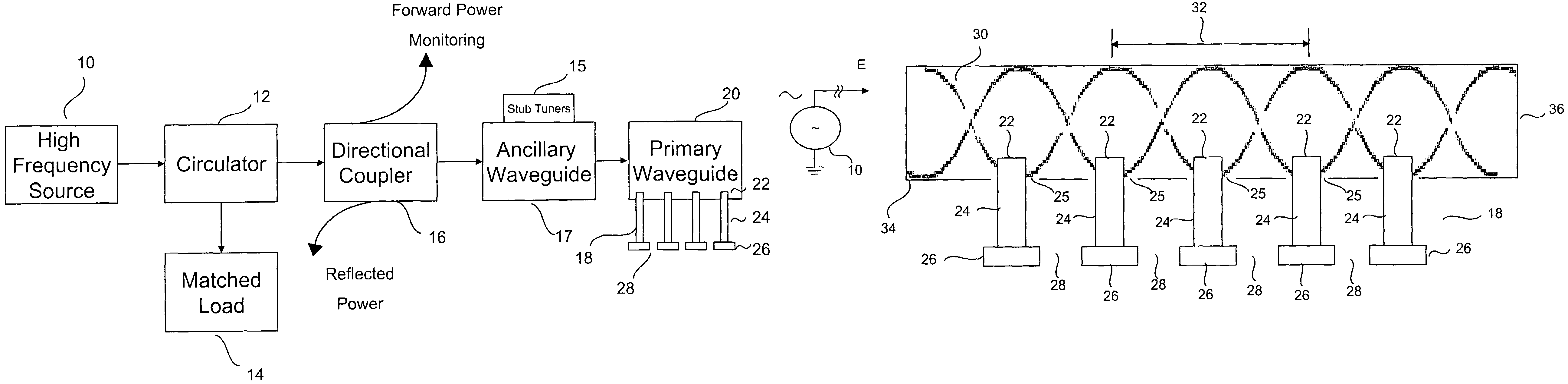
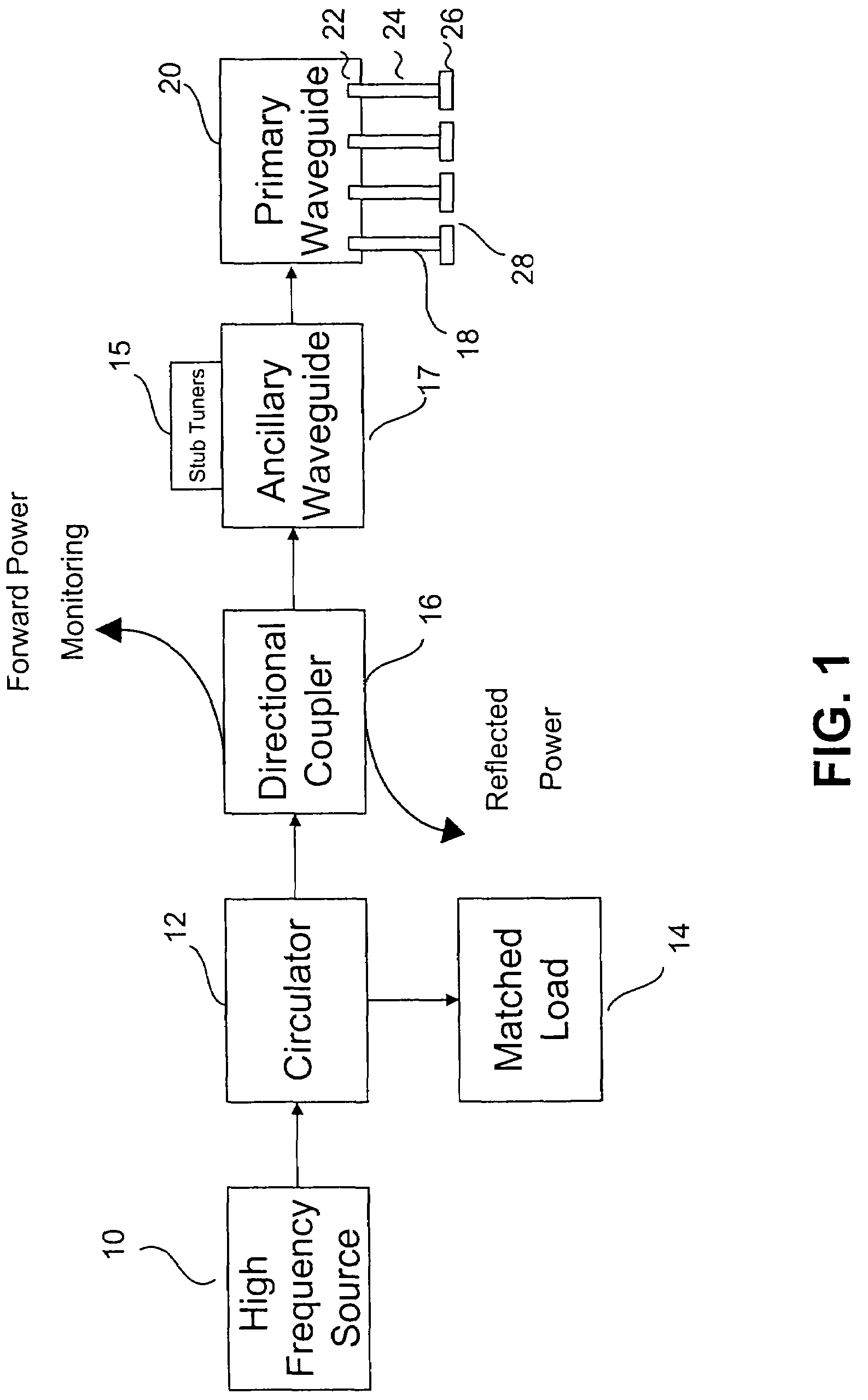
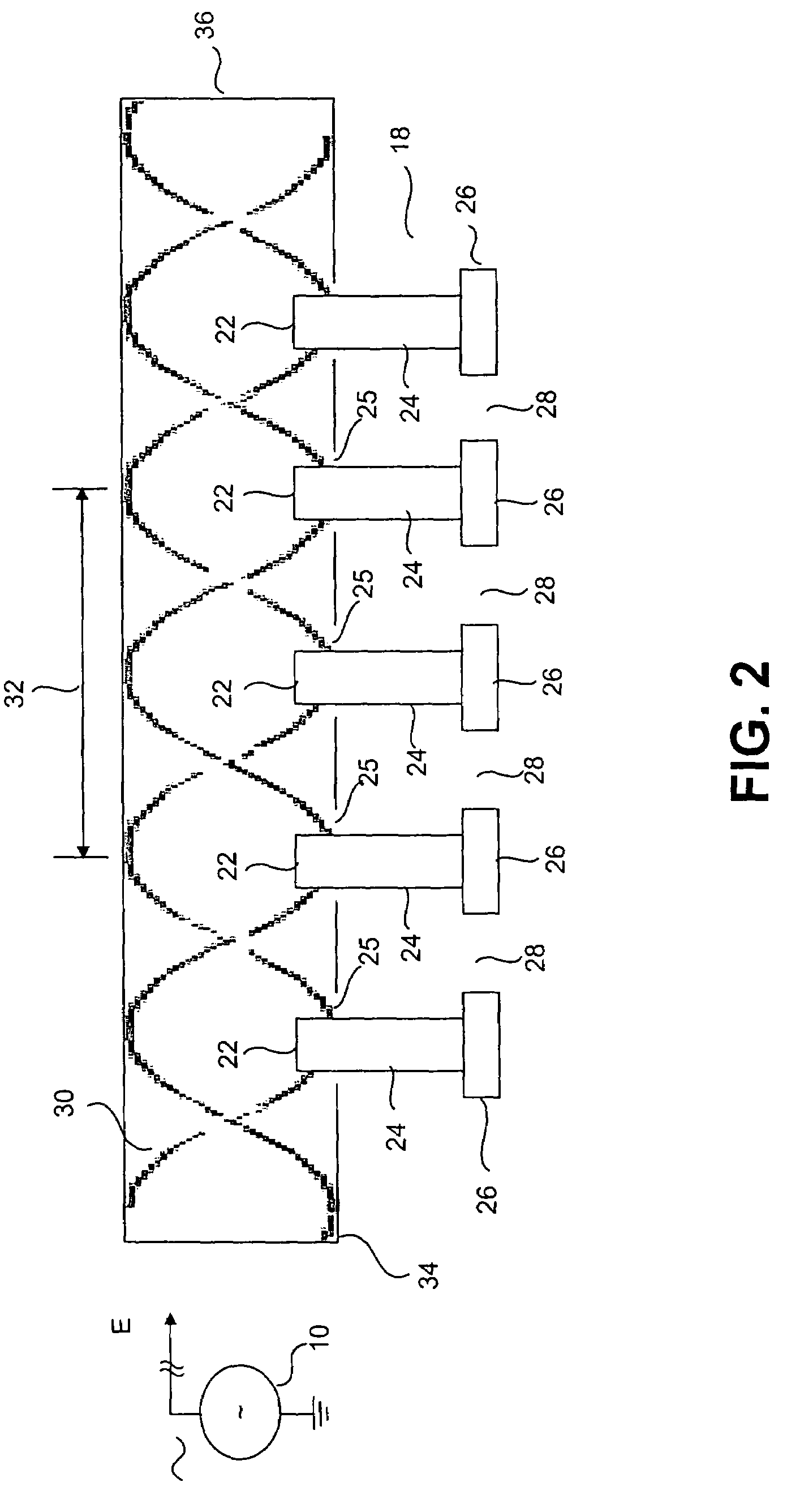
[0023]A system and method for producing plasma at atmospheric pressure is described herein with reference to FIGS. 1-4. Referring first to FIG. 1, a high frequency source 10 such as a magnetron provides power in the 1 GHz range through a primary waveguide 20 to a plasma area outside the primary waveguide 20. The high frequency source 10 can be protected from reflected power by a circulator 12 having matched loads 14 and a directional coupler 16 disposed between the high frequency source 10 and the primary waveguide 20. The use of a directional couplers 16 and a circulator 12 having a matched load 14 for protecting a high frequency source 10 from reflected power is well known and should be understood by persons having ordinary skill in the art.

[0024]One or more stub tuners 15 can be particularly configured with an ancillary waveguide 17 between the directional coupler 16 and the primary waveguide 20 to produce a high amplitude standing wave in the primary waveguide 20. A plurality of...


PUM


Abstract

A method and apparatus for producing a distributed plasma at atmospheric pressure. A distributed plasma can be produced at atmospheric pressure by using an inexpensive high frequency power source in communication with a waveguide having a plurality particularly configured couplers disposed therein. The plurality of particularly arranged couplers can be configured in the waveguide to enhance the electromagnetic field strength therein. The plurality of couplers have internal portions disposed inside the waveguide and spaced apart by a distance of ½ wavelength of the high frequency power source and external portions disposed outside the waveguide and spaced apart by a predetermined distance which is calculated to cause the electromagnetic fields in the external portions of adjacent couplers to couple and thereby further enhance the strength of the electromagnetic field in the waveguide. Plasma can be formed in plasma areas defined by gaps between electrodes disposed on the external portions.

Description

FIELD OF THE INVENTION[0001]The present invention relates to the field of plasma production and more particularly to economical production of plasma at atmospheric pressure.BACKGROUND OF THE INVENTION[0002]In the semiconductor industry, plasmas are used to deposit materials on and etch materials from work-pieces to form specific electronic components on the work-piece substrate. Plasmas that are used in semiconductor fabrication processes are commonly generated by ionizing a gas in a vacuum chamber. For example, a gas can be introduced into an evacuated plasma chamber where the work-piece is located. A strong electric field can be applied to the plasma chamber. The gas can form a plasma in an excitation region by undergoing an electrical breakdown under the influence of the strong electric field.[0003]The electric field in such chambers is typically either capacitively or inductively coupled to the gas to remove electrons therefrom. In capacitively coupled plasma generators, the ele...

Claims


Application Information

Patent Timeline
Patent Type & Authority Patents(United States)
IPC IPC(8): H01J25/50H01P7/06
CPCH01J37/32192H05H1/24H01J37/32211H01J37/32201H05H1/46H05H1/4622H05H1/463
Inventor OKSUZ, LUTFIELLINGBOE, ALBERT ROGERS
Owner DUBLIN CITY UNIVERSITY
Why Eureka
Try Eureka