Phase frequency detector and phase-locked loop

a phase frequency detector and phase-locked loop technology, applied in oscillation comparator circuits, pulse automatic control, instruments, etc., can solve problems such as 0.25 ns static phase error

Active Publication Date: 2009-09-22
MEDIATEK INC +1
View PDF4 Cites 35 Cited by
  • Summary
  • Abstract
  • Description
  • Claims
  • Application Information

AI Technical Summary

Problems solved by technology

If the duration of the pulse width Tpup is 1 ns, it results in a static phase error of 0.25 ns.

Method used


Image

  • Phase frequency detector and phase-locked loop
  • Phase frequency detector and phase-locked loop
  • Phase frequency detector and phase-locked loop

Examples


Embodiment Construction

[0024]The following description is of the best-contemplated mode of carrying out the invention. This description is made for the purpose of illustrating the general principles of the invention and should not be taken in a limiting sense. The scope of the invention is best determined by reference to the appended claims.

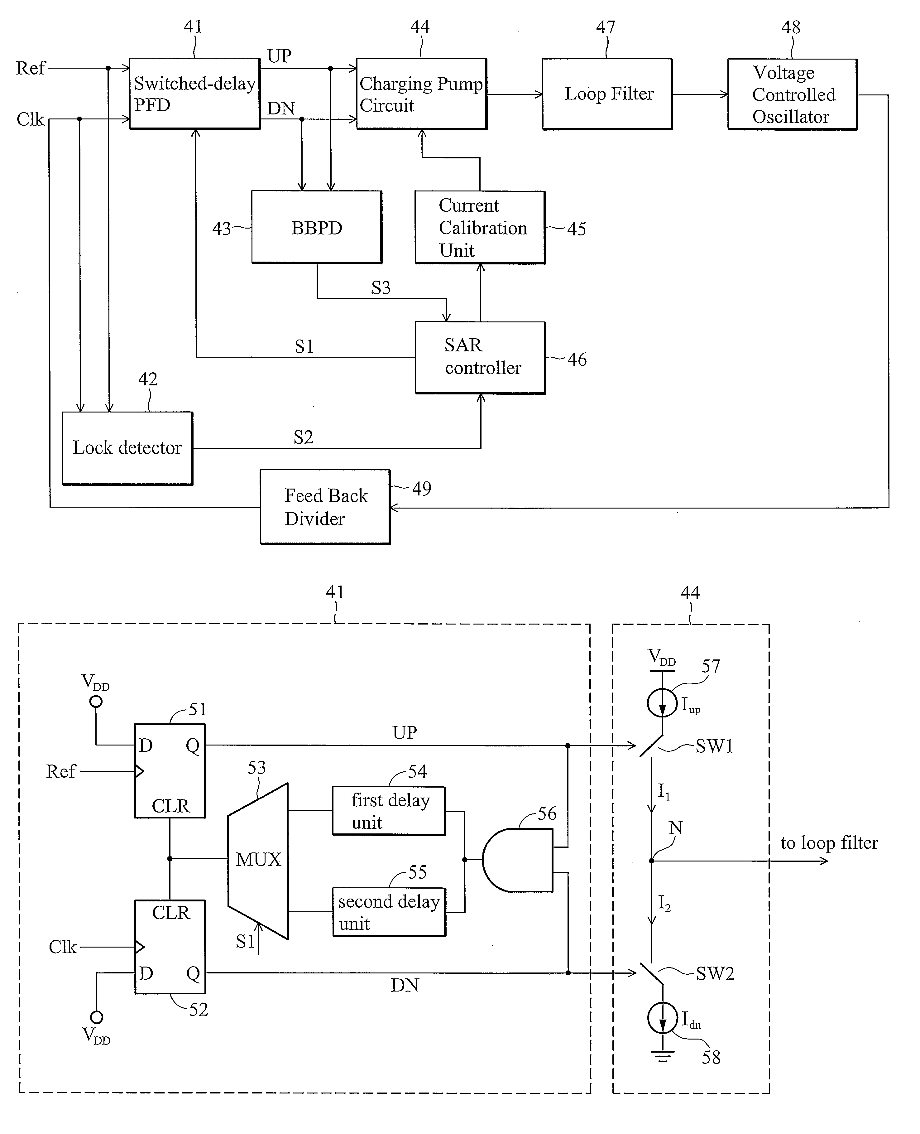
[0025]FIG. 4 is a block diagram of a PLL device with switched-delay phase frequency detector in accordance with an embodiment of the invention. The PLL device comprises a switched-delay phase frequency detector 41, a lock detector 42, a bang bang phase detector (BBPD) 43, a charge pump circuit 44, a current calibration unit 45, a SAR controller 46, a loop filter 47, a voltage-controlled oscillator 48 and a feedback divider 49. The switched-delay phase frequency detector 41 receives a reference clock signal Ref and a feedback clock signal Clk and measures the phase and frequency difference therebetween to output an up signal (UP) and a down signal (DN). The switched-del...


PUM


Abstract

A phase frequency detector with two different delays is disclosed herein. The phase detector comprises a first D flip-flop, a second D flip-flop, a first delay unit and a second delay unit. The first D flip-flop receives a reference signal to output an up signal. The second D flip-flop receives a clock signal to output a down signal. The first delay unit delays the received signal with a first delay. The second delay unit delays the received signal with a second delay. When the reference signal synchronizes with the clock signal and the charge pump currents are calibrated, the high-level pulse widths of the up signal and the down signal are determined based on the first delay, and when the reference signal does not synchronize with the clock signal and the charge pump currents are not calibrated, the high-level pulse widths of the up signal and the down signal are determined based on the second delay.

Description

CROSS REFERENCE TO RELATED APPLICATIONS[0001]This application claims the benefit of U.S. Provisional Application No. 60 / 896,285, filed at Mar. 22, 2007, incorporated herein by reference.BACKGROUND OF THE INVENTION[0002]1. Field of the Invention[0003]The present invention relates to a phase-locked loop device and more particularly to a phase-locked loop device with switched-delay phase frequency detector.[0004]2. Description of the Related Art[0005]A phase-locked loop (PLL) device, is a major component applied in frequency generators, wireless receivers, communication devices and so on. Referring to FIG. 1. FIG. 1 is a schematic diagram of a conventional PLL device. PFD unit 11 receives a reference clock signal REF_CK and a feedback clock signal FBK_CK and measures the phase and frequency difference therebetween to output phase difference signals, UP and DN. Charge pump circuit 12 receives and transforms the phase difference signals UP and DN into a current to charge loop filter 13. ...

Claims


Application Information

Patent Timeline
Patent Type & Authority Patents(United States)
IPC IPC(8): H03L7/00
CPCH03D13/004H03L7/0891H03L7/095H03L7/0896H03L7/0898H03L7/0895
Inventor LIU, SHEN-LUANLIANG, CHE-FUCHEN, HSIN-HUA
Owner MEDIATEK INC
Why Eureka
Try Eureka