Outdoor high velocity wall and floor fans

Active Publication Date: 2009-09-29
CHIEN LUEN INDS
View PDF9 Cites 21 Cited by
  • Summary
  • Abstract
  • Description
  • Claims
  • Application Information

AI Technical Summary

Benefits of technology

[0022]A tenth objective of the present invention is to provide high velocity wall and floor fans, devices, systems and methods of operation for outdoor use, with an improved gear mechanism to give long life operation at big torques on the gear.
[0023]A eleventh objective of the present invention is to provide high velocity wall and floor fans, devices, systems and methods of operation for outdoor use, having components made out of stainless steel for durability and extended lifespan.
[0024]A twelfth objective of the present invention is to provide high velocity wall and floor fans, devices, systems and methods of operation for outdoor use, having a powder coat finish on all parts to reduce corrosion.
[0025]An thirteenth objective of the present invention is to provide high velocity wall and floor fans, devices, systems and methods of operation for outdoor use, th

Problems solved by technology

However, the traditional wall plug useable fans have housings with openings therethrough that do not allow for outdoor use.
The traditional fan motors can easily overheat since the tendency is run undersized motors to reduce electricity demand, where the heating motors must be continuously vented to eliminate overheating effects that would result in damage to the fans, such as burn-out and potentially fires.
Thus these fans cannot be used outdoors or in wet damp environments since the motor housings allow for moisture to enter through vents, and openings in the housings.
Thus, traditional wall and pedestal mounted fans are not useful in outdoor settings such as in backyards, around pools, in gazebos, and the like.
Still furthermore, traditional fans will have closed bottoms in their motor housings which will tend to allow for moisture to accumulate inside and potentially damage the motor and electrical components inside the housing.
Additiona

Method used


Image

  • Outdoor high velocity wall and floor fans
  • Outdoor high velocity wall and floor fans
  • Outdoor high velocity wall and floor fans

Examples


Embodiment Construction

[0054]Before explaining the disclosed embodiments of the present invention in detail it is to be understood that the invention is not limited in its applications to the details of the particular arrangements shown since the invention is capable of other embodiments. Also, the terminology used herein is for the purpose of description and not of limitation.

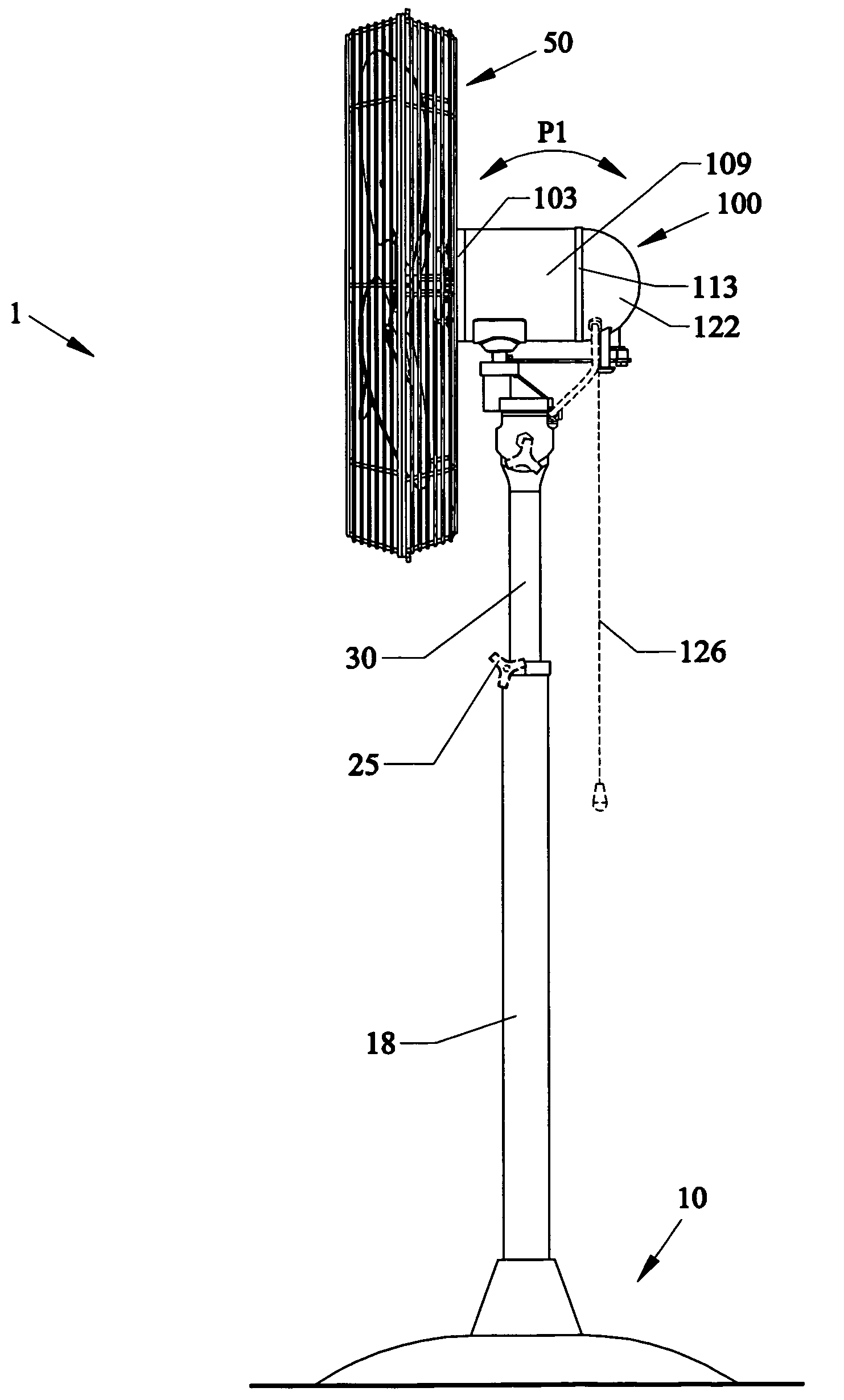
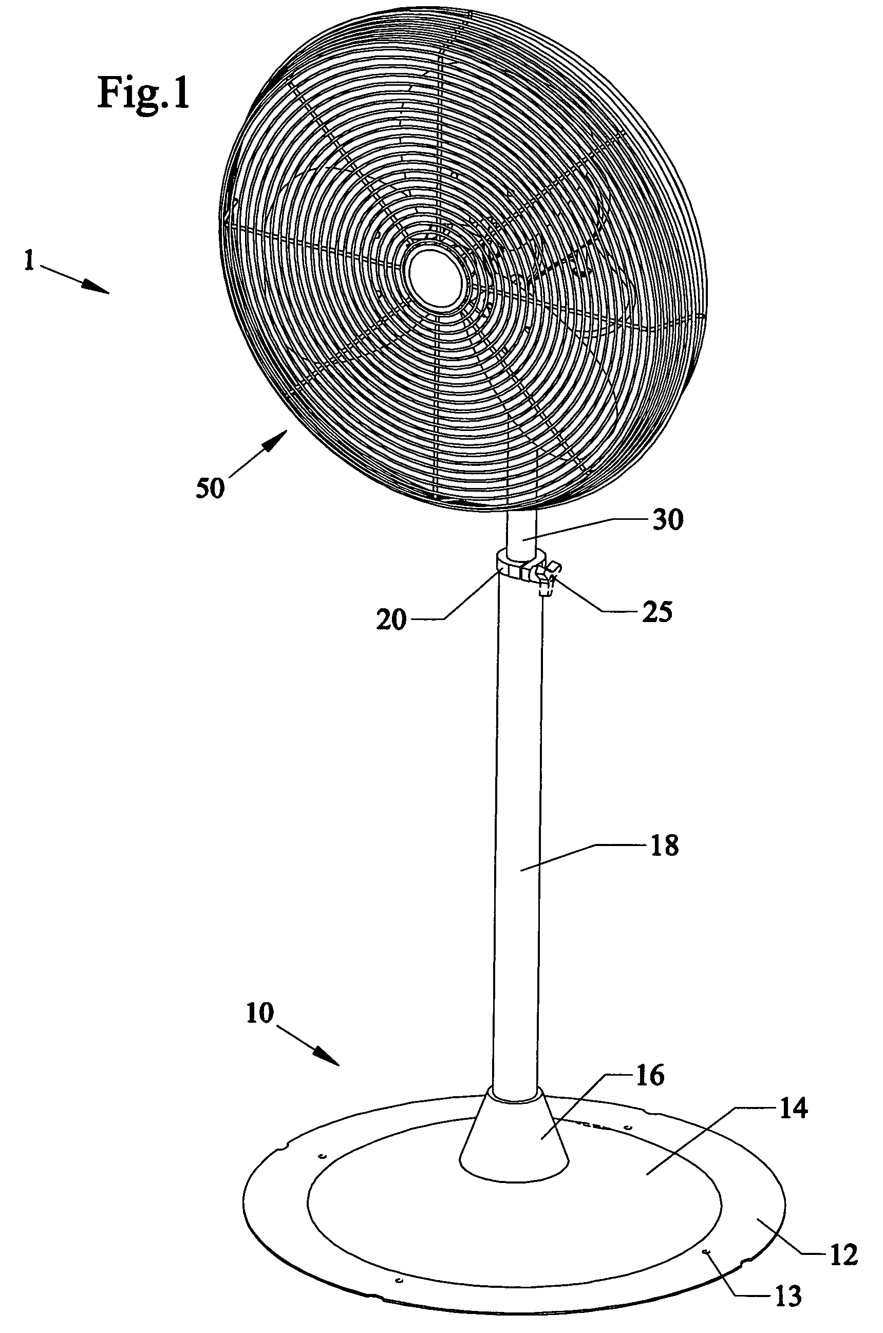
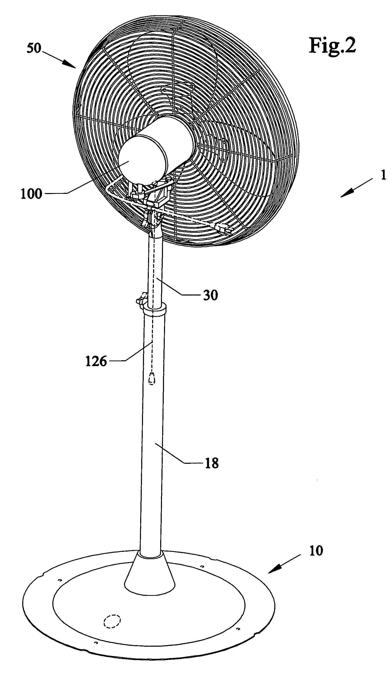
[0055]A list of the components will now be described.[0056]1 Pedestal Fan Embodiment[0057]10 Base[0058]12 Flat outer base ring[0059]13. Fastener holes to mount base[0060]14 middle domed base portion[0061]16 cone base connector[0062]18 lower tubular support[0063]20 upper end of lower tubular support[0064]25 rotatable tightening knob with internal protruding member To lock telescoping upper and lower tubular supports[0065]30 upper tubular support[0066]31 elongated oval opening for pivoting knob 35 in flat flange 32[0067]32 flat flange connector on upper tubular support[0068]33 through-holes for fasteners[0069]35 pivoting position tigh...


PUM


Abstract

Outdoor high velocity wall and pedestal mounted fans, devices, apparatus, systems and methods of operation. The fans can have water resistant motor housings with at most one rear wall located opening for allowing a power cord to pass therethrough. The switches and pull chains are connected to the fan only through the bottom of the motor housing. The bottom of the motor housing can have a drainage hole for allowing excess moisture to drain therefrom. The motor housing can be stainless steel. Additionally, the motor housing can have a powder coat finish on all parts to reduce corrosion. The motor can be an oversized inverted outdoor rated oscillating motor having improved gear mechanisms for big torques and reduces heat rise during fan operation. The fan can operate under hot and cold temperature extremes as well as during wet and dry environmental conditions.

Description

[0001]This invention is a Continuation-In-Part of U.S. Patent Application 29 / 261,391 filed Jun. 13, 2006, and this invention claims the benefit of priority to U.S. Provisional Patent Application Ser. No. 60 / 834,520 filed Jul. 31, 2006.FIELD OF INVENTION[0002]This invention relates to fans, in particular to high velocity wall and floor fans for outdoor use, and related devices, systems and methods of operation.BACKGROUND AND PRIOR ART[0003]Electrical fans have been in use for many years. There have been many designs in the field for 100 years on industrial, pedestal and wall fans. Traditional types of electrical fans that run off 120 volt power supplies have included pedestal based fans and mounted fans, where the motors are mounted adjacent to and generally behind the fan rotors. These traditional fans are well known for indoor use.[0004]However, the traditional wall plug useable fans have housings with openings therethrough that do not allow for outdoor use. For example, traditiona...

Claims


Application Information

Patent Timeline
IPC IPC(8): F04D29/26
CPCF04D29/701F04D25/105
Inventor BUCHER, JOHN C.CARTER, WILLIAMRICKER, CHAD
Owner CHIEN LUEN INDS
Why Eureka
Try Eureka