Model railroad track scrubbing car

a technology for railroad tracks and cars, applied in the direction of toys, transportation and packaging, ways, etc., can solve the problems of uncleaning, derail, and car to split a switch

Active Publication Date: 2009-10-06
LEONOWICZ ROBERT SCOTT
View PDF0 Cites 8 Cited by
  • Summary
  • Abstract
  • Description
  • Claims
  • Application Information

AI Technical Summary

Benefits of technology

[0011]The present invention relates to a model railroad track scrubbing car including a pair of absorbent, compressible and resilient rollers mounted to a pair of fixed horizontal axles under the chassis of the car. Each roller has an inner sleeve so that it freely rotates about its axle. The active working surfaces of each roller compress against, frictionally engage and wrap around the tops and side of the track rails. Each roller is set to a scrub angle of about 30° so that it rotates at a reduced rate relative to the speed of the train to provide rotating circumferential working engagement with the rails and across-the-rail scrubbing action and possibly some along-the-rail scrubbing action. The rollers simultaneously rotate and scrub the tops and sides of the rails. The scrub angle increases the width of the working areas for individual track rails. The scrub angle and height of the roller axles relative to the track are adjustable to set the amount of roller compression and scrubbing action against the track rails, and allow for different length or diameter rollers.
[0012]An advantage of the present track scrubbing car is the effectiveness of its scrubbing action. Each roller has a compressible resilient layer that rubs against and wraps around the top and side surfaces of the track rails. The compressed wrapped shape of the rollers increases the active working engagement area between the roll and the rail, and thus the friction and scrubbing or rubbing action of the roller. Each roller is also angled relative to the track rails and normal axis of the car. This scrub angle produces an effective amount of scrubbing action to clean the track rails. Rollers that are free to rotate and are generally perpendicular to the track rails, produce little or no scrubbing action. The forces between the track and roller simply rotate the roller so that the speed of the outer surface of the roller is generally the same as the speed of the train along the track. The scrub angle produces across-the-rail scrubbing action due to the lateral movement of the outer surface of the roller relative to the rails. The scrub angle also slows the rotation of the roller, which may generate along-the-rail scrubbing action. Although the along-the-rail scrubbing action may help clean the rails, the across-the-rail scrubbing action is believed to be particularly effectively in scrubbing both the sides and tops of the rails. A scrub angle of about 10° to 50° and preferably 30° simultaneously produces a good amount of scrubbing action and roller rotation to effectively clean the track rails.
[0013]Another advantage of the track scrubbing car is the adjustability of its scrubbing action. The roller axles are lowered or raised relative to the track rails by a height adjustment mechanism to increase or decrease the amount of scrubbing action. The rollers can be set for more vigorous scrubbing action when necessary by lowering them, or less vigorous scrubbing action to extend the life of the rollers by raising them. The amount of scrubbing or rubbing action can also be adjusted depending on the amount of dirtiness or type of dirt or grime on the rails. Too little compression or scrubbing force can cause uneven cleaning. Too much compression or scrubbing force can cause the car to split a switch and derail. One of the two rollers can be removed to decrease the amount of scrubbing action and force need to pull the track cleaning car. When one of the roller is removed, the scrub angle of the remaining roller can be increased beyond 30° if desired. This adjustability allows a person to custom set the amount of scrubbing action appropriate for their particular model railroad layout and specialty track components.

Problems solved by technology

Too little compression or scrubbing force can cause uneven cleaning.
Too much compression or scrubbing force can cause the car to split a switch and derail.

Method used


Image

  • Model railroad track scrubbing car
  • Model railroad track scrubbing car
  • Model railroad track scrubbing car

Examples


Embodiment Construction

[0033]While this invention is susceptible of embodiment in many different forms, the drawings show and the specification describes in detail a preferred embodiment of the invention. It should be understood that the drawings and specification are to be considered an exemplification of the principles of the invention. They are not intended to limit the broad aspects of the invention to the embodiment illustrated.

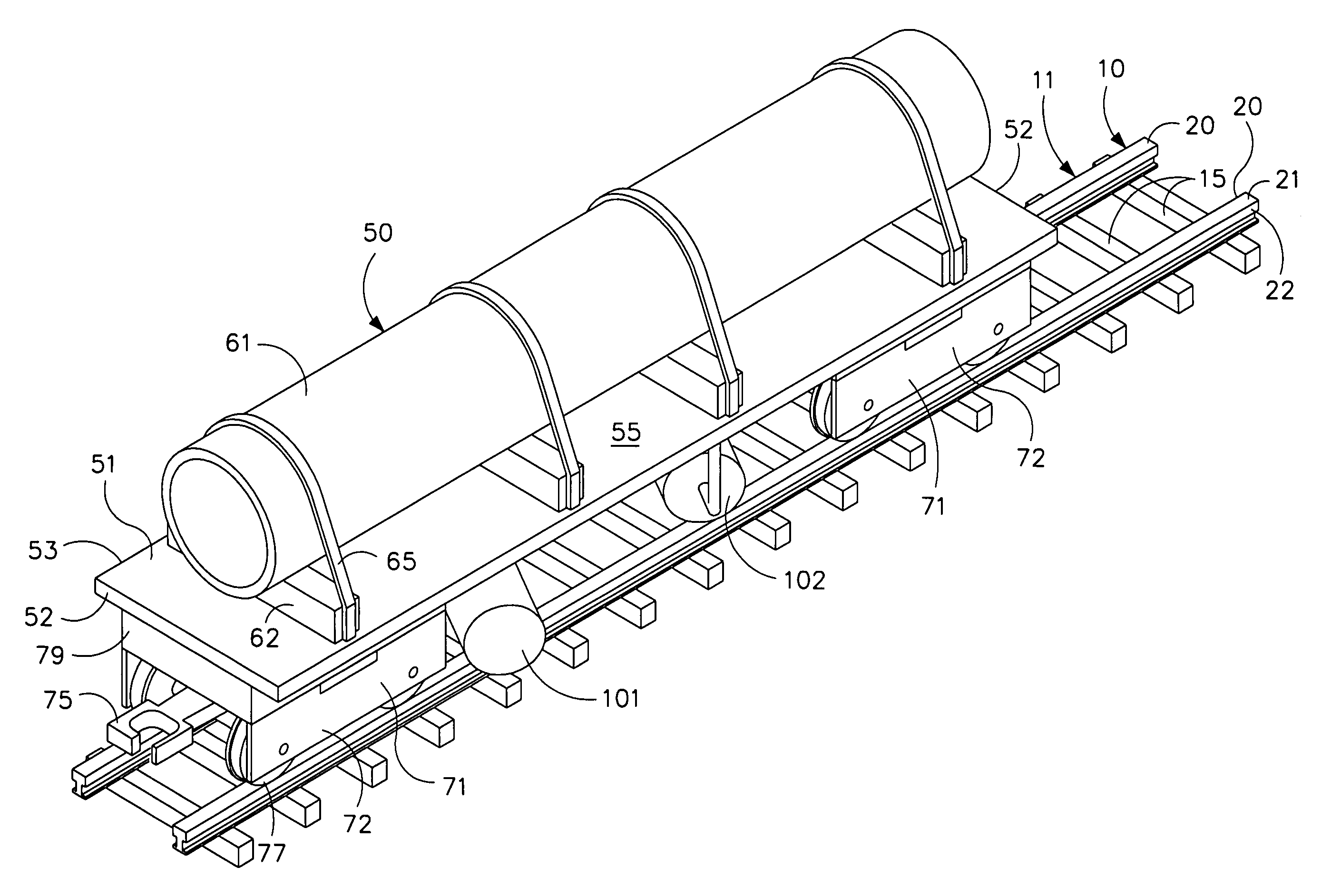
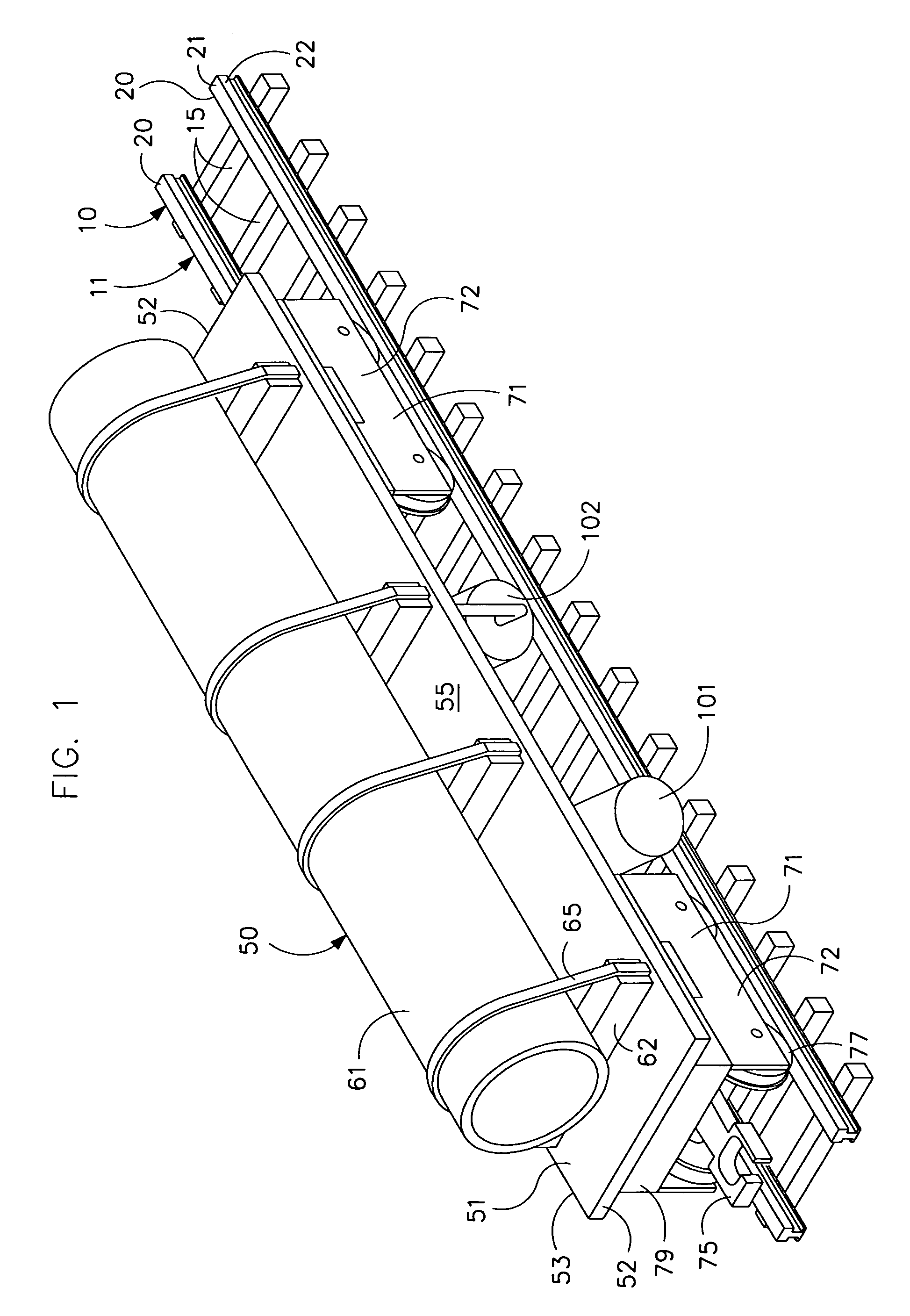
[0034]The present track scrubbing car is intended to clean the track of an assembled electric model railroad layout. The layout is formed by joining a number of pieces of track 10 together, and includes a transformer connected to an electric power supply such as via an electric cord connected to the wall outlet of a home or building. The transformer typically includes a power control to control the speed of the locomotive engine of a train traveling along the layout. The transformer also includes positive and negative or ground leads that are electrically connected to the trac...


PUM


Abstract

The invention is a model railroad track scrubbing car with rollers set at a scrub angle of about 30° to scrubs the tops and sides of the track rails. The rollers freely rotate about fixed axle under the chassis of the weighted car. Each roller is preferably a conventional paint roller with an inner sleeve and an outer tubular roll made of an absorbent, compressible, resilient foam material. The active working surfaces of each roller compress against, frictionally engage and deform around the tops and sides of the rails. The scrub angle and rollers provide across-the-rail scrubbing action and possibly along-the-rail scrubbing action. The circumferential working areas of the rollers are wider than the width of their associated track rails. The scrub angle and height of the roller axle above the track rails are adjustable to set the amount of roller compression and scrubbing action against the track rails.

Description

TECHNICAL FIELD OF THE INVENTION[0001]This invention relates to a model railroad track scrubbing car with resiliently compressible, absorbent rollers that engage and scrub the top and sides of the track rails, where each roller is rotatably secured to a fixed axle set to a scrub angle to provide rotating circumferential working engagement with the rails and across-the-rail scrubbing action.BACKGROUND OF THE INVENTION[0002]Model railroading is a growing industry, and has become more high-tech in recent years. The locomotives and engines include solid state electric circuits that include contact roller pickups on their underside that rest on the track rails. The track rails are made of steel, brass, or nickel-silver, and are energized with a variable voltage and electric current supplied by a power source and transformer. One rail is energized to a first, positive or higher voltage. Another rail is energized to a second, grounded, negative or lower voltage. Nonconductive or insulated ...

Claims


Application Information

Patent Timeline
Patent Type & Authority Patents(United States)
IPC IPC(8): A63H19/15
CPCE01B31/02A63H19/15Y10S104/01
Inventor LEONOWICZ, ROBERT SCOTT
Owner LEONOWICZ ROBERT SCOTT
Why Eureka
Try Eureka