Constant-rate volatile material dispensing device

Inactive Publication Date: 2009-10-06
STUCKI ANDRE
View PDF22 Cites 11 Cited by
  • Summary
  • Abstract
  • Description
  • Claims
  • Application Information

AI Technical Summary

Benefits of technology

[0016]A further object of the present invention is to provide a volatile material dis

Problems solved by technology

By quickly spraying a quantity of small particulates, manual systems have the advantage of fast delivery, however they do not provide automatic, continuous dispersal, but require the consumer's initiation each time dispensing is desired.
Active powered systems, while automatically providing continuous dispersal, do not provide a constant level of intensity.
This type was so prone to spills that it is no longer commercially available.
These too are messy, prone to spillage, and potentially

Method used


Image

  • Constant-rate volatile material dispensing device
  • Constant-rate volatile material dispensing device
  • Constant-rate volatile material dispensing device

Examples


Embodiment Construction

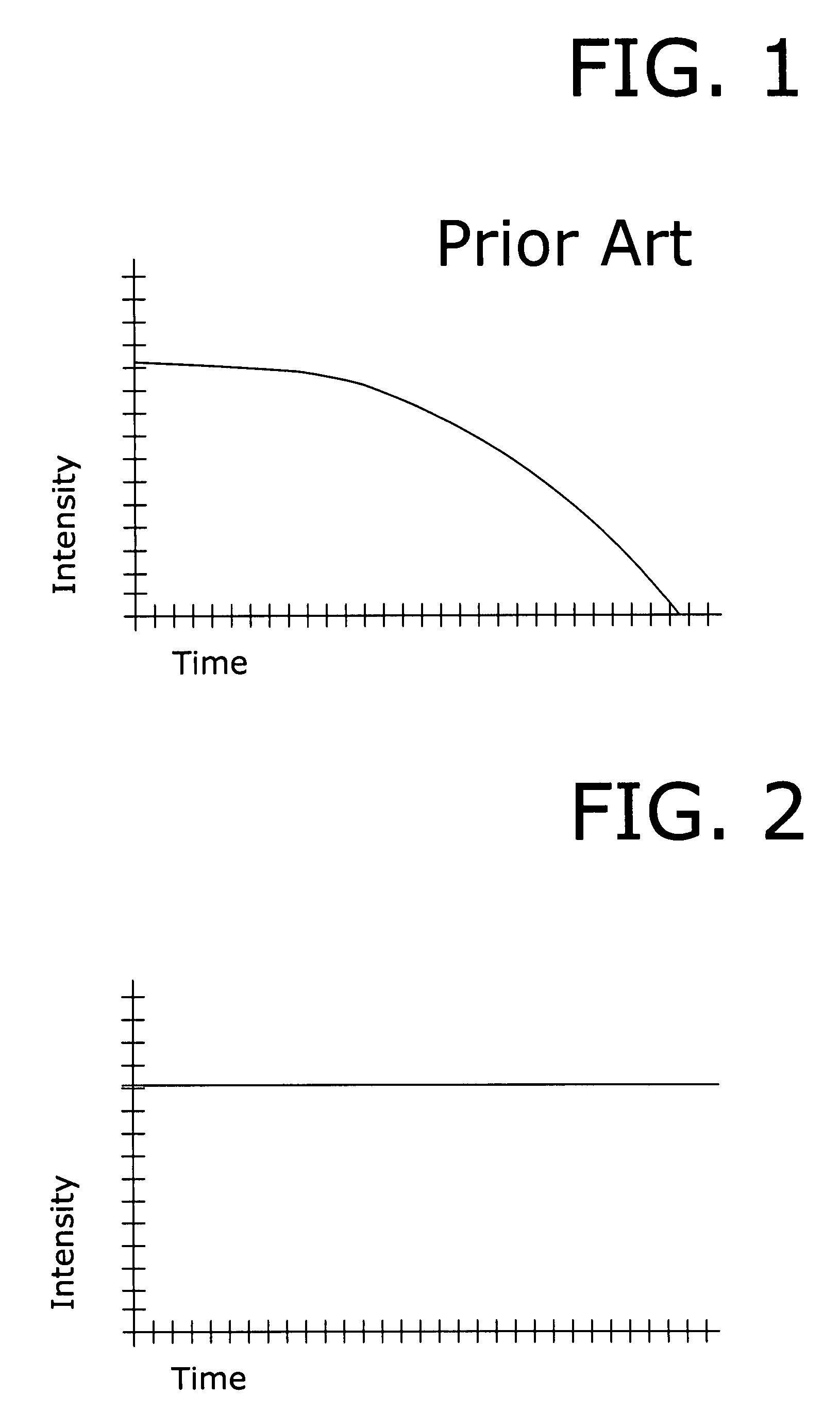
[0024]Shown throughout the figures, the present invention is directed towards an improved, effective, and easy to use volatile material dispensing device. Whereas previous devices exhibited a varying, decreasing vapor intensity over time as demonstrated in FIG. 1, the present improved volatile material dispensing device provides constant vapor intensity over time, as shown in FIG. 2, with a time-release dispensing mechanism delivering a controlled, consistent flow, with an appropriate drip rate.

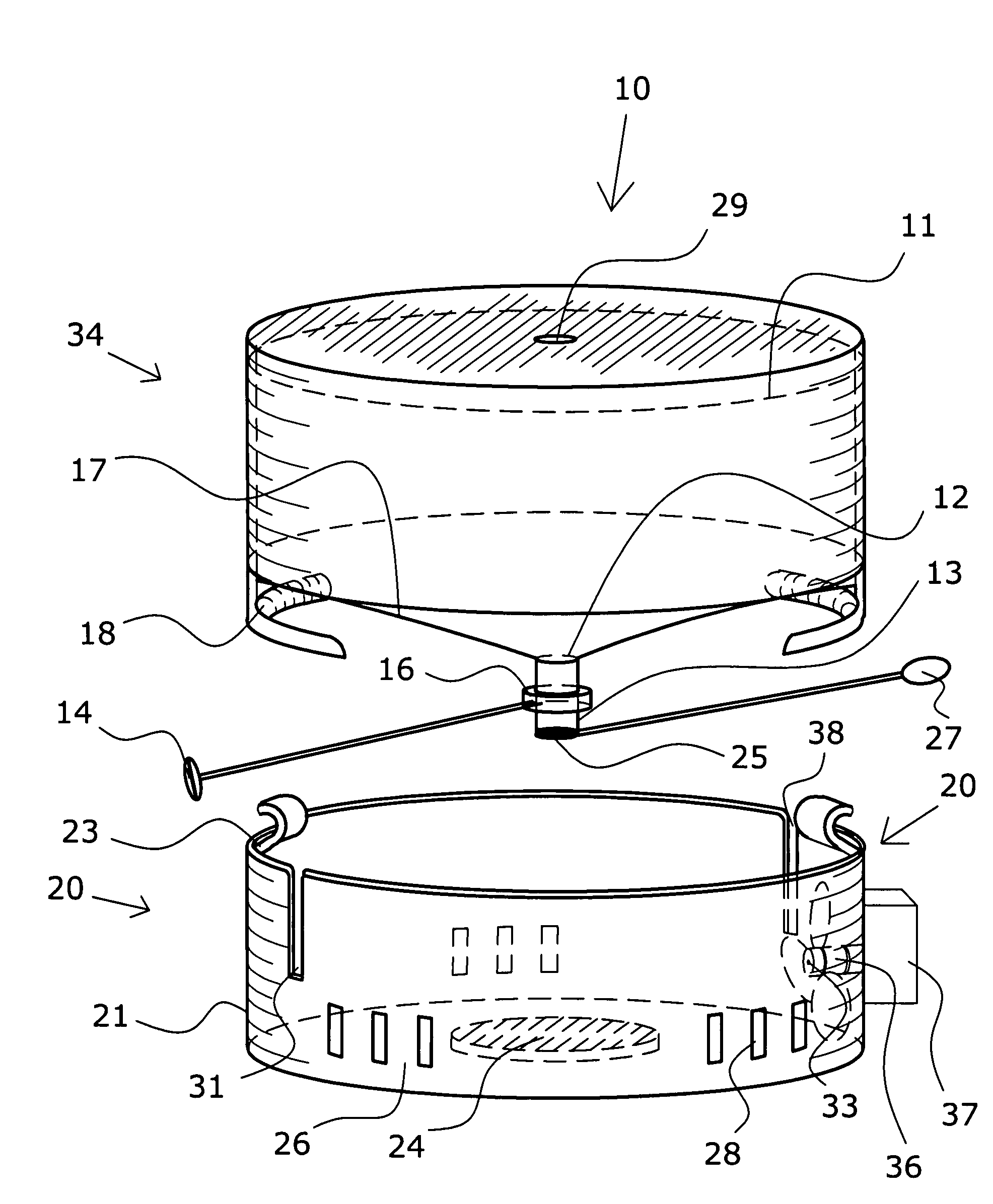
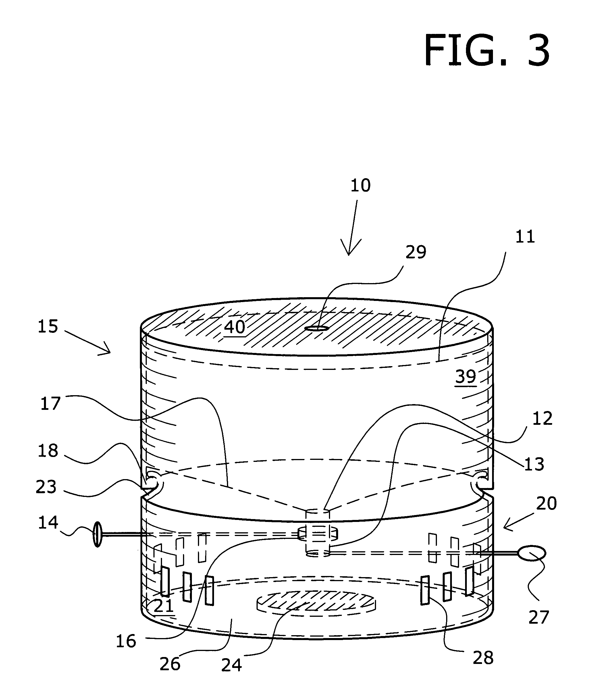
[0025]Referring now to FIG. 3, a volatile material dispensing device, shown generally as reference number 10, is illustrated in accordance with a preferred embodiment of the present invention. As shown, the volatile material dispensing device 10 comprises both an upper reservoir 15 and a lower housing 20, with a tube 13 fluidly connecting them.

[0026]Reservoir 15 comprises side wall 39, top 40, and bottom wall 41. The interior surface of reservoir 15 defines a cavity 17 that is designed to hol...


PUM

PropertyMeasurementUnit
Poweraaaaaaaaaa
Flow rateaaaaaaaaaa
Volatilityaaaaaaaaaa

Abstract

A volatile material dispensing device is provided, including a reservoir containing a supply of any one of numerous volatile materials having an outlet port with attached tube through which the volatile material flows, a valve and valve adjustment mechanism to control the flow rate through the tube, a lower housing incorporating a pad to receive the volatile material, and a tear-off tab that initially seals the tube and prevents flow until removed by the consumer. Optionally, the device may include an active mechanism, such as a fan, to aid dispersal of the volatile material. The device gives the user control of the intensity of the vapor by providing the ability to adjust the flow through the valve with the valve adjustment mechanism. The device also provides constant vapor intensity over time with a time-release dispersing mechanism delivering a controlled, consistent flow, with an appropriate drip rate.

Description

CROSS-REFERENCE TO RELATED APPLICATION[0001]This application claims the benefit of co-pending U.S. Provisional Patent Application Ser. No. 60 / 791,133, filed Apr. 11, 2006, which is incorporated herein in its entirety.BACKGROUND OF THE INVENTION[0002]1. Field of the Invention[0003]The present invention relates generally to volatile material dispensing devices, and more particularly, to a volatile material dispensing device for dispensing at a constant rate.[0004]2. Description of the Prior Art[0005]A number of attempts have been made to devise volatile material dispensing devices. These devices dispense perfumed fluid, aromatic oils, odor deodorizers, disinfectants, scented gels, insecticides, or the like, that scent or modify the atmosphere. Typically these devices are used in a room, vehicle, or other confined space. Volatile material dispensing devices that are designed to produce a pleasing aroma, often called air fresheners, have become common household products. Not only do the...

Claims


Application Information

Patent Timeline
IPC IPC(8): B01F3/04
CPCA01M1/2033A61L9/122A61L9/12A01M1/2055Y10S261/88
Inventor STUCKI, ANDRE
Owner STUCKI ANDRE
Why Eureka
Try Eureka