Communications network for a metropolitan area

a technology for communication networks and metropolitan areas, applied in the field of communication networks, can solve the problems of inability to meet the needs of customers, etc., and achieve the effect of improving the communication network

Inactive Publication Date: 2009-10-06
RPX CLEARINGHOUSE
View PDF5 Cites 63 Cited by
  • Summary
  • Abstract
  • Description
  • Claims
  • Application Information

AI Technical Summary

Benefits of technology

[0045]It is an object of the present invention to provide an improved communications network for a metropolitan area.

Problems solved by technology

Still further, because of the complex configuration of the metropolitan access network, signals must undergo many protocols and physical conversions as they traverse the network.
However, as FSAN is to be an open system interconnect (OSI) layer-2 (i.e. ATM-based) network requiring at least one virtual circuit to each end-user, to ensure that the quality of service (QoS) committed to that end-user is maintained, it will still entail significant complexity to operate.
Prior art metropolitan optical networks are costly, difficult-to-deploy, and error-prone.
They are also unreliable, complex and power-hungry.
Multiple, somewhat incompatible systems make up the overall offering.
This results in long set-up times and complex administration systemsc. Error-pronei.
Both the initial installation and the setting up of connections in response to customer requirements include complex systems with lots of human interaction, which provides plenty of scope for errorsd.
Non-ideally integrated OAM systems, difficult recovery from some fault conditionse.
The very scale and ubiquity of their plant makes them very cautious and conservative and often they will only move to adopt new things once they are forced to by their more aggressive, agile and nimble competition.
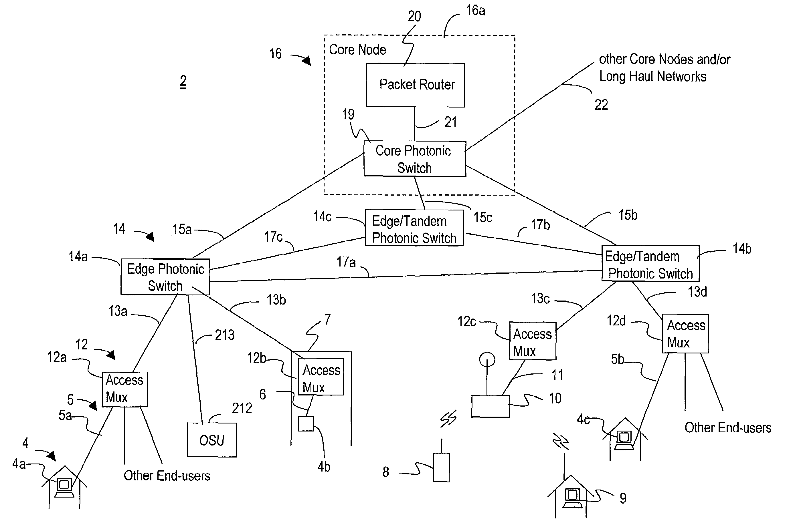
In particular, the use of routing at intermediate nodes permits dynamic traffic reconfiguration, but at the expense of complex routers, potential traffic degradation due to QoS issues associated with heavy traffic transients on the routers, leading to packet loss, or delay.
The ILEC's multiple buildings means that they have the real estate to house any expansion, but only at the cost of maintaining those large (expensive to upkeep) buildings and the equipment within those buildings.
In particular further packet traffic bandwidth aggregation may occur via tandem routers, resulting in higher data “fills” in the transport pipes.
This multiple level of concatenation tends to make for costly, difficult-to-deploy, unreliable, complex, power-hungry and error-prone networks.
They are likely to have a major but not ubiquitous presence in a given metro area and have limited fiber, fiber rights-of-way, so may have difficulty reaching whole sub-sections of a given metro area.
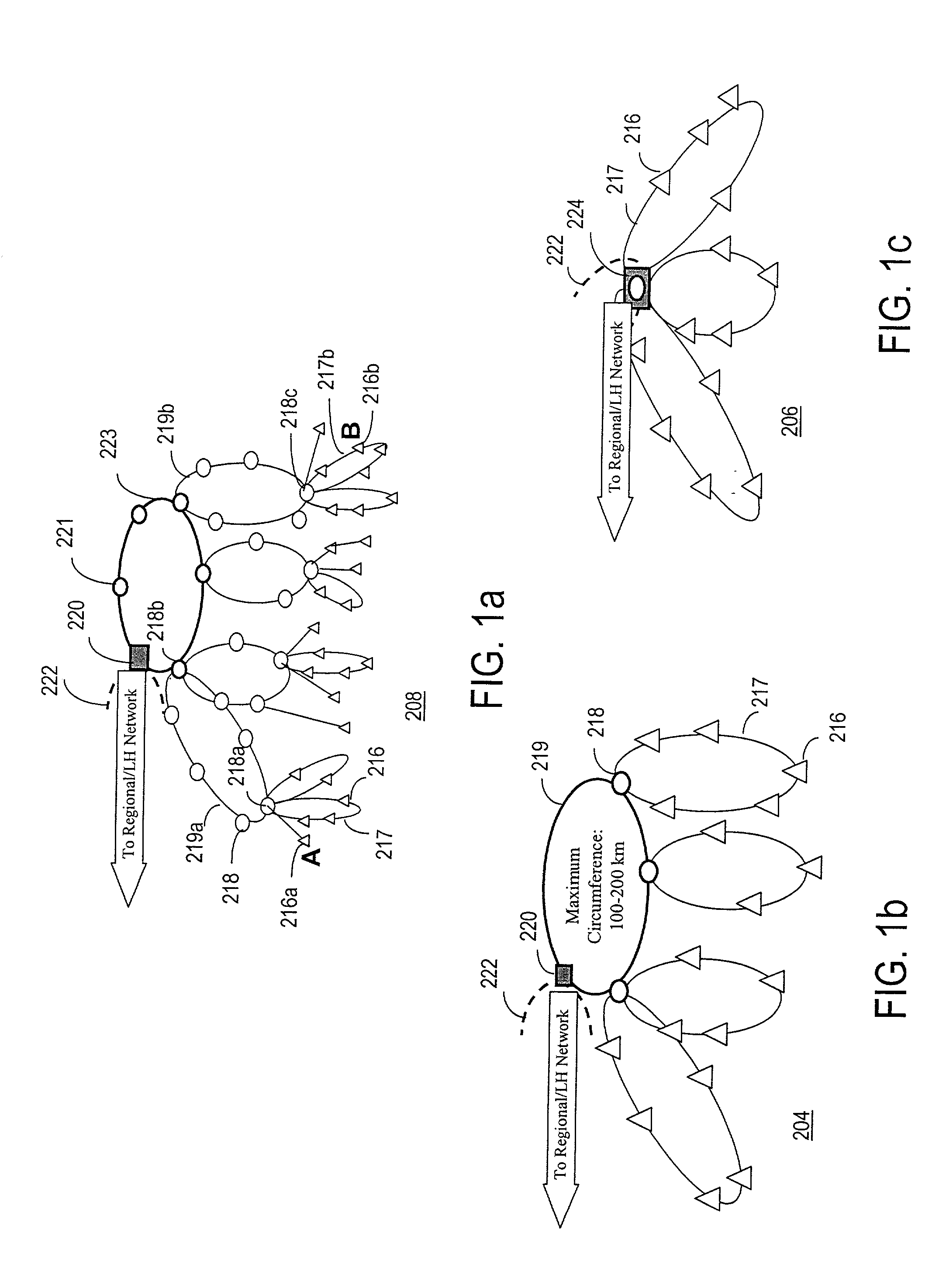
For business customers, where two or more routes exist into the business site a ring can be implemented but often, especially for the smaller business and residence, a ring cannot be implemented and point-to-point or add-drop buss structures have to be used.
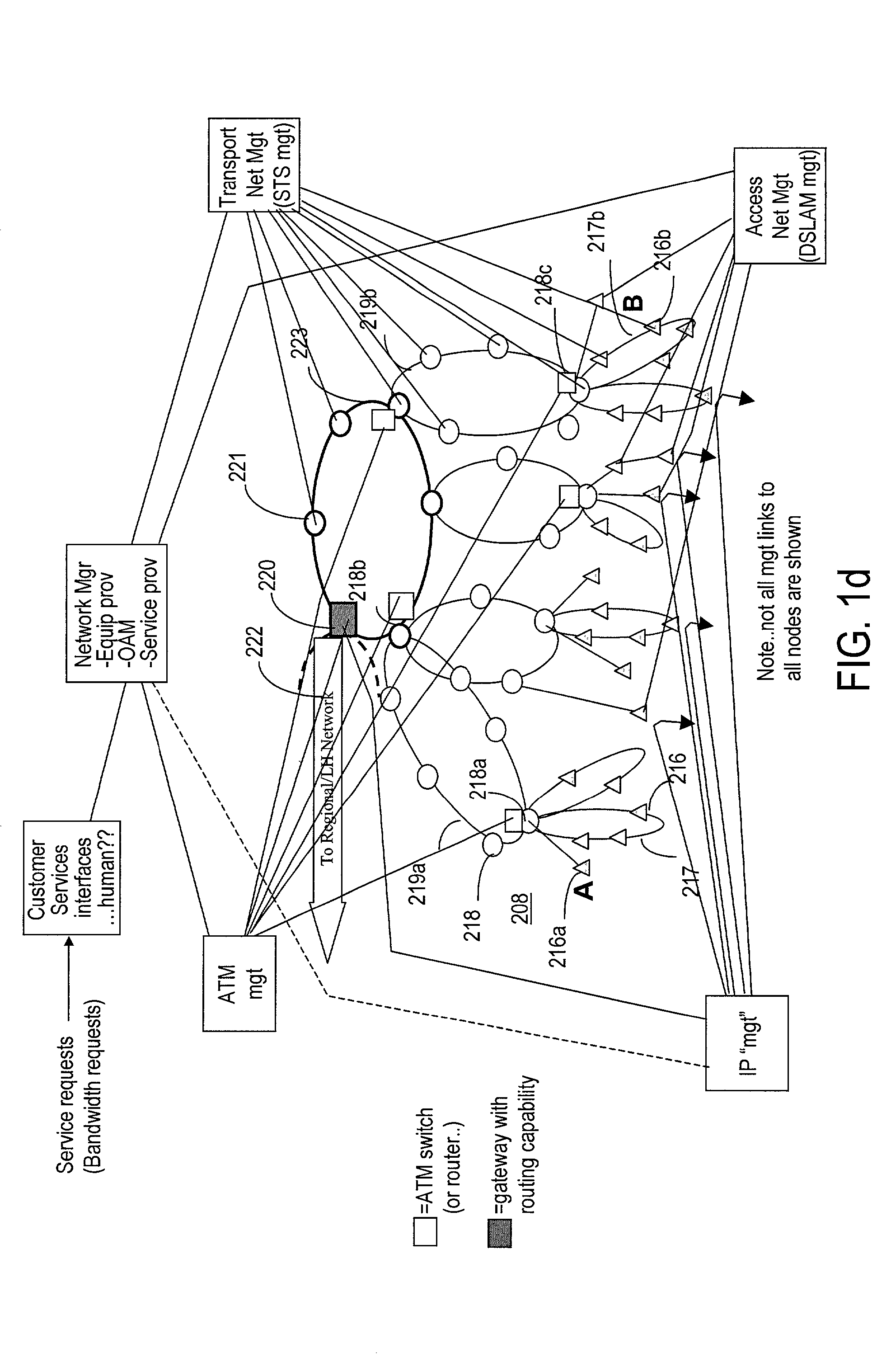
Whilst it is apparent that a practical ILEC network can be much more complex than what is described here, by employing several stages of rings, and potentially deploying ATM switches and / or routers in other network nodes, this further increases the complexity and cost of implementing this style of network, so only the relatively simple (but still complex) tasks of setting up the network path of FIG. 2a will be described.
This results in a very high efficiency flexible network, but at the cost of poor overload / peak traffic behaviour, due to massive QoS fall-off at high loads, due to the packet discards at intermediate nodes, which triggers the TCP layer to re-try transmission, resulting in much of the network traffic being lost and resent, just at the time of peak load when the network cannot tolerate inefficient operation.
This is seen by end users as a massive reduction in network performance at peak times. In addition such a network is relatively costly per unit of delivered bandwidth, forcing the extreme use of technique to maximize the bandwidth utilization efficiency in an attempt to achieve a cost-effective way forward.
Such an approach is incompatible with direct photonic connections with minimal hops.

Method used


Image

  • Communications network for a metropolitan area
  • Communications network for a metropolitan area
  • Communications network for a metropolitan area

Examples


Embodiment Construction

[0092]Referring to FIG. 3, a communications network for a metropolitan area is comprised of three types of network nodes: an access multiplexer 12, an edge photonic switch 14, or edge / tandem photonic switch (since some of the optical carriers transitting a photonic switch may have come not from the local access but rather further out edge photonic switches), this switch also being also referred to herein as simply a photonic switch, and the core node or nodes 16. The access multiplexers 12 provide multiplexing of Ethernet packets from end-users 4 over their local loops 5, which carry 100 bT or 1 GE Ethernet fiber based multiplexed service connections or multi-service “VDSL-like” connections, and can act as the Ethernet mapping points for legacy services or connections, where these are capable of being carried in a high quality packet format, and maps all of these onto one or more Sparse-DWDM (S-DWDM) wavelengths, or a fiber. Sparse-DWDM is so-called because, although the carrier wav...


PUM


Abstract

A communications network for a metropolitan area is disclosed. The network is comprised of three basic types of nodes: an access multiplexer, a photonic switch, and a core node. The access multiplexer provides multiplexing of data packets from end-users onto at least one sparse wavelength division multiplexed (SWDM) wavelength. The SWDM wavelengths are carried over fiber cable to the photonic switches, which consolidate these wavelengths into dense wavelength division multiplexed (DWDM) wavelengths for transmission to the core node. The core nodes include a photonic switch (PSX) and a service-aware terabit router core for routing packets within the metropolitan area via the network or out to a long haul network. The photonic switches and core nodes are capable of switching at the wavelength, group of wavelength, and fiber levels.

Description

[0001]The present application is related in subject matter to co-pending U.S. application Ser. No. 09 / 511,065, entitled “Switch For Optical Signals”, filed on Feb. 23, 2000, assigned to the Assignee of the present invention and hereby incorporated by reference herein in its entirety. The present application is also related in subject matter to co-pending U.S. application Ser. No. 09 / 703,631 entitled “Optical Switching System for Switching Optical Signals in Wavelength Groups”, filed on Nov. 2, 2000, assigned to the Assignee of the present invention and hereby incorporated by reference herein in its entirety. The present application is also related in subject matter to co-pending U.S. application Ser. No. 09 / 703,002 entitled “Photonic Network Node”, filed on Feb. 15, 2001, assigned to the Assignee of the present invention and hereby incorporated by reference herein in its entirety. The present application is also related in subject matter to co-pending U.S. application Ser. No. 09 / 45...

Claims


Application Information

Patent Timeline
Patent Type & Authority Patents(United States)
IPC IPC(8): H04B10/00H04Q11/00
CPCH04Q11/0066H04Q2011/0084H04Q2011/0075
Inventor GRAVES, ALAN F.CUNNINGHAM, IAN M.STARK, RYANFELSKE, KENT E.HOBBS, CHRISWATKINS, JOHN H.
Owner RPX CLEARINGHOUSE
Why Eureka
Try Eureka