Surface treating appliance

a surface treatment and appliance technology, applied in the direction of cleaning filter means, cleaning equipment, electric equipment installation, etc., can solve the problems of difficult manoeuvrability of the upright vacuum cleaner, difficult to point the cleaner in a new direction, and difficult to maneuver the upright vacuum cleaner around the area in which it is used, etc., to achieve the effect of improving manoeuvrability

Active Publication Date: 2009-10-13
DYSON TECH LTD
View PDF48 Cites 44 Cited by
  • Summary
  • Abstract
  • Description
  • Claims
  • Application Information

AI Technical Summary

Benefits of technology

[0007]The present invention seeks to provide a surface treating appliance with improved manoeuvrability.
[0009]The provision of a rolling support surface and a linkage which allows the handle to be rotated or twisted about its longitudinal axis, in the manner of a corkscrew, improves manoeuvrability and ensures a smooth transition between the forward running and turning positions. Thus, the usability of the appliance is improved.
[0010]Preferably a joint is provided between the handle and the cleaner head, which joint may be lockable in order to prevent the cleaner head from turning when the appliance is in an upright position. This feature provides stability to the appliance when it is stationary.
[0012]Advantageously, the support assembly is arranged so that the diameter of the central portion is greater than that of the end portions, so that the outer surface has a spherical or barrel shape. This greater facilitates the user in turning the appliance in a new direction. The support assembly may house one or more components of the appliance.

Problems solved by technology

Conventional upright vacuum cleaners have a disadvantage in that they can be difficult to manoeuvre about an area in which they are used.
They can be pushed and pulled easily enough, but pointing the cleaner in a new direction is more difficult.
While stick vacs are lighter weight and can be easier to manoeuvre than traditional upright cleaners, they generally have a small dust separator, a lower power motor and smaller filters, if any filters at all, and thus their improved manoeuvrability comes with the drawback of a lower specification.

Method used


Image

  • Surface treating appliance
  • Surface treating appliance
  • Surface treating appliance

Examples


Embodiment Construction

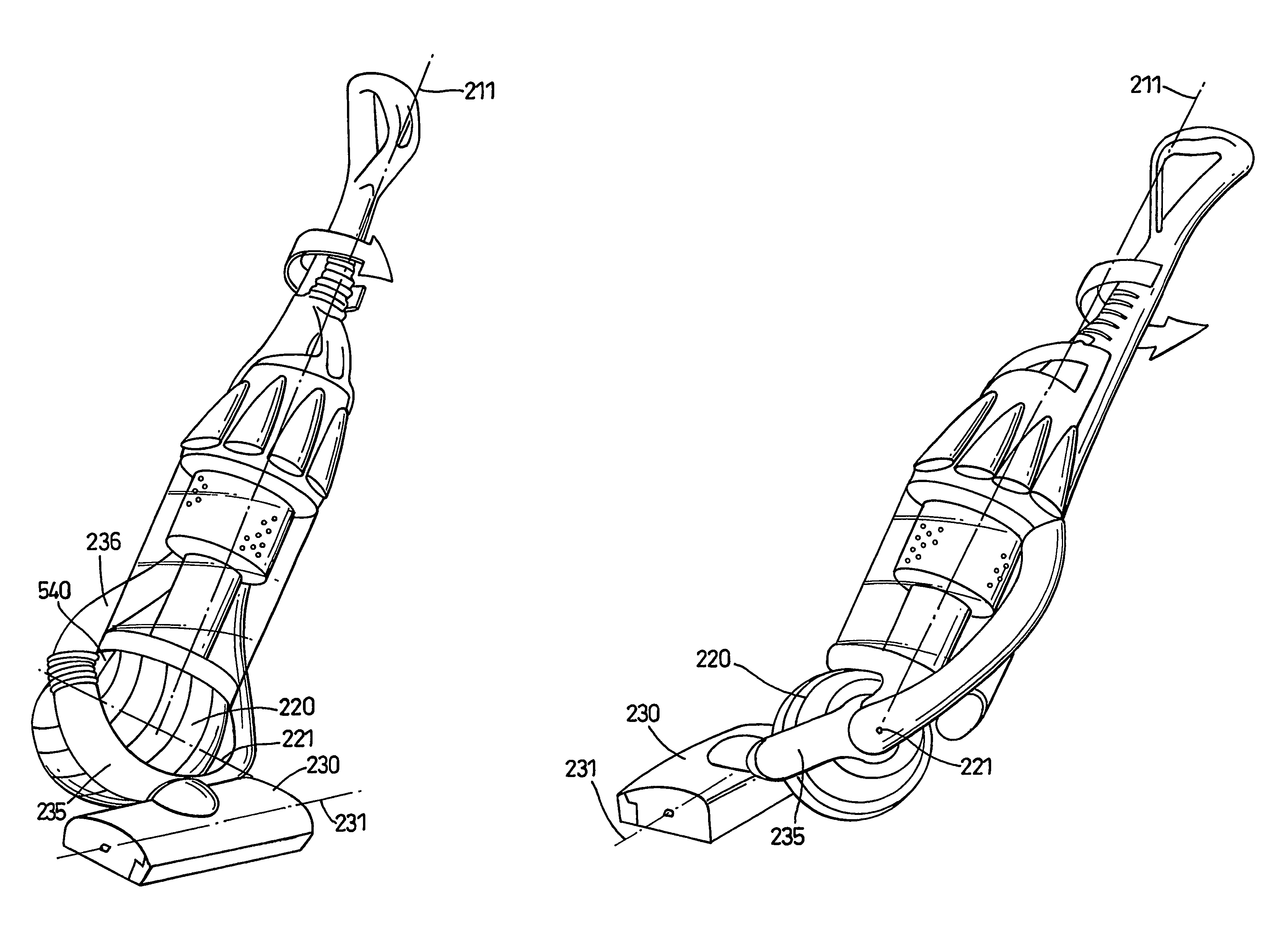
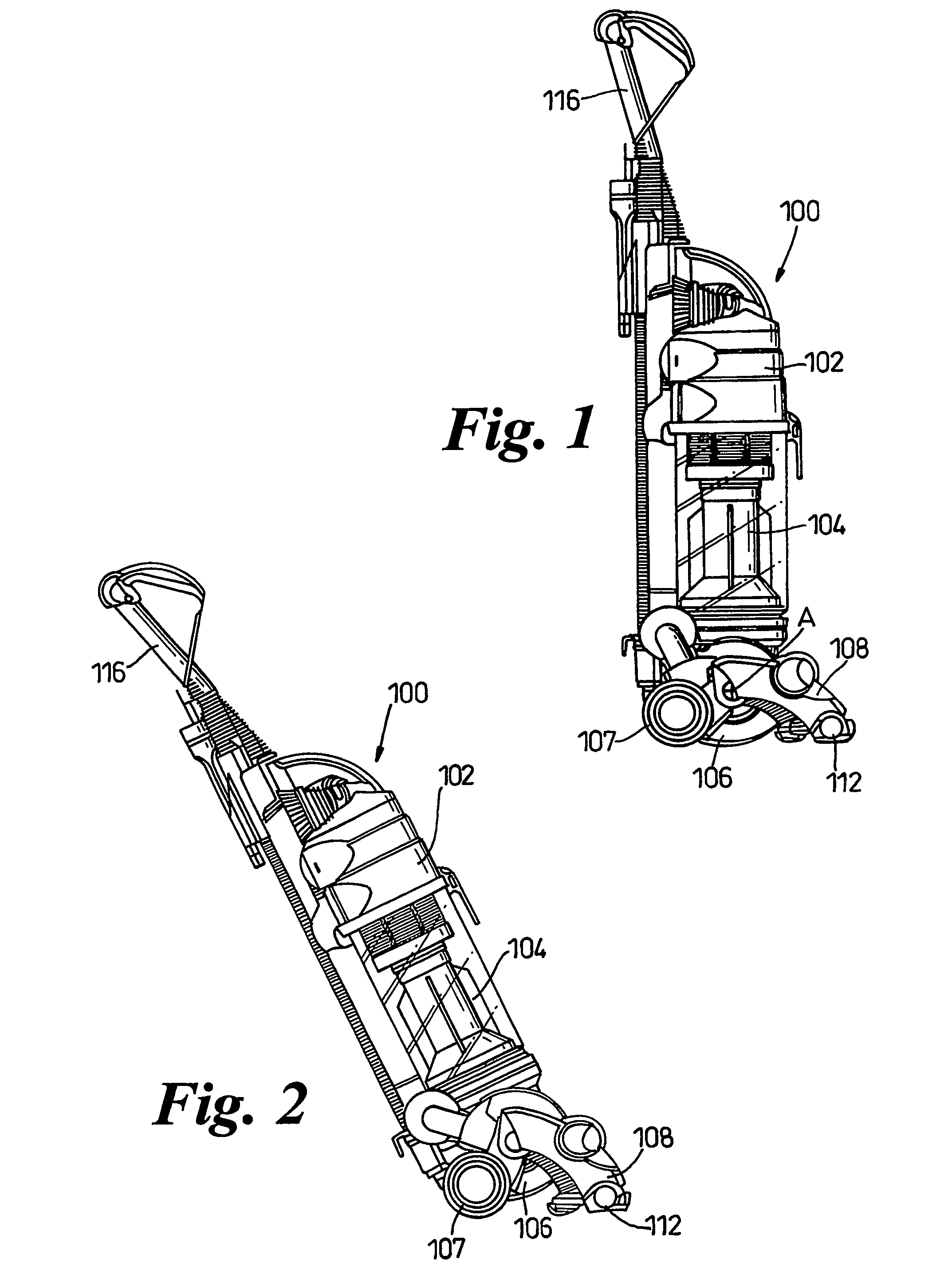
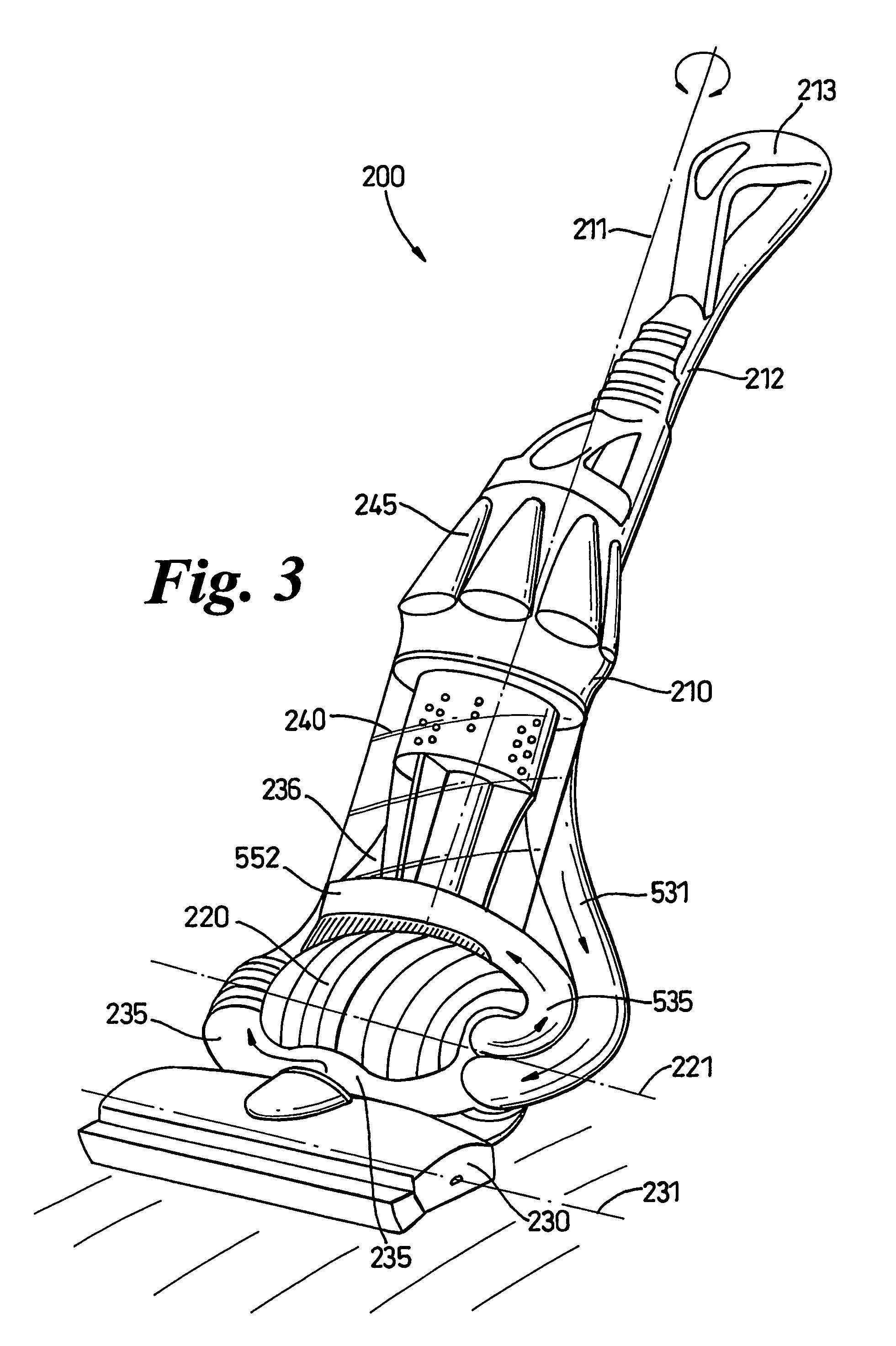
[0032]FIGS. 3-13 show a first embodiment of a vacuum cleaner 200 with a main body 210, a roller assembly 220 and a cleaner head 230.

[0033]The cleaner head 230, as in a conventional upright vacuum cleaner, serves to treat the floor surface. In this embodiment, it comprises a housing with a chamber for supporting a brush bar 232 (FIG. 6). The lower, floor-facing side of chamber has an air inlet slot 233 and the brush bar 232 is rotatably mounted in the chamber such that bristles on the brush bar 232 can protrude through the inlet slot 233 and can agitate the floor surface over which the cleaner head 230 passes. The brush bar 232 is rotatably driven by a dedicated motor 242 positioned on the cleaner head 230. A drive belt connects the motor 242 to the brush bar 232. This avoids the need to provide a driving connection between the suction fan and the brush bar. However, it will be appreciated that the brush bar can be driven in other ways, such as by a turbine which is driven by incomin...


PUM


Abstract

A surface treating appliance, such as a vacuum cleaner, includes a handle, a surface treating head and a support assembly. The support assembly is rollably mounted to the main body for allowing the main body to be rolled along a surface. A linkage is provided between the main body and the surface treating head and arranged such that rotating the main body about its longitudinal axis causes the surface treating head to turn in a new direction. The support assembly may house a component of the appliance, such as a motor, and may accommodate a fluid inlet for receiving fluid flow and a fluid outlet for exhausting fluid. The handle may carry the main body of the appliance.

Description

FIELD OF THE INVENTION[0001]This invention relates to a surface treating appliance, such as a vacuum cleaner.BACKGROUND OF THE INVENTION[0002]Surface treating appliances such as vacuum cleaners and floor polishers are well known. The majority of vacuum cleaners are either of the ‘upright’ type or of the ‘cylinder’ type, called canister or barrel cleaners in some countries. An example of an upright vacuum cleaner manufactured by Dyson Limited under the name DC04 (“DC04” is a trade mark of Dyson Limited) is shown in FIG. 1. The vacuum cleaner comprises a main body 102 which houses the main components of the vacuum cleaner. A lower part 106 of the main body houses a motor and fan for drawing dirty air into the machine and the main body also houses some form of separating apparatus 104 for separating dirt, dust and other debris from a dirty airflow drawn in by the fan. The main body 102 also houses filters for trapping fine particles in the cleaned airflow. A cleaner head 108 is rotatab...

Claims


Application Information

Patent Timeline
Patent Type & Authority Patents(United States)
IPC IPC(8): A47L9/00A47L5/28A47L9/02A47L9/24
CPCA47L5/28A47L9/0054A47L9/242A47L9/02A47L9/009A47L9/22A47L9/30A47L9/12
Inventor COURTNEY, STEPHEN BENJAMIN
Owner DYSON TECH LTD
Why Eureka
Try Eureka