Ultrasonic diagnostic apparatus

a diagnostic apparatus and ultrasonic technology, applied in the field of ultrasonic diagnostic apparatus, can solve the problems of complicated operation and expertise in setting and achieve the effect of easy setting of the optimum cross section

Inactive Publication Date: 2009-10-20
HITACHI LTD
View PDF17 Cites 15 Cited by
  • Summary
  • Abstract
  • Description
  • Claims
  • Application Information

AI Technical Summary

Benefits of technology

[0007]The present invention advantageously provides an ultrasonic diagnostic apparatus in which an optimum cross section can be easily set.
[0012]The left ventricle of the heart contains characteristic portions such as an apex section of heart and a mitral valve. The major-axis setter may set the left ventricle major axis using, for example, these characteristic portions. Alternatively, a position of the center of mass of the left ventricle cavity and a position of an inner cavity surface may be used for setting the left ventricle major axis. With the above structure, because the cross sectional image former set at least one of the four-cavity cross section, two-cavity cross section, and the minor-axis cross section based on the basis cross section, it is possible to set the optimum cross section without a complicated cross setting operation of a cross section by the user.

Problems solved by technology

Because of this, the operation to set an optimum cross section becomes complicated and requires expertise.

Method used


Image

  • Ultrasonic diagnostic apparatus
  • Ultrasonic diagnostic apparatus
  • Ultrasonic diagnostic apparatus

Examples


Embodiment Construction

[0025]A preferred embodiment of the present invention will now be described referring to the drawings.

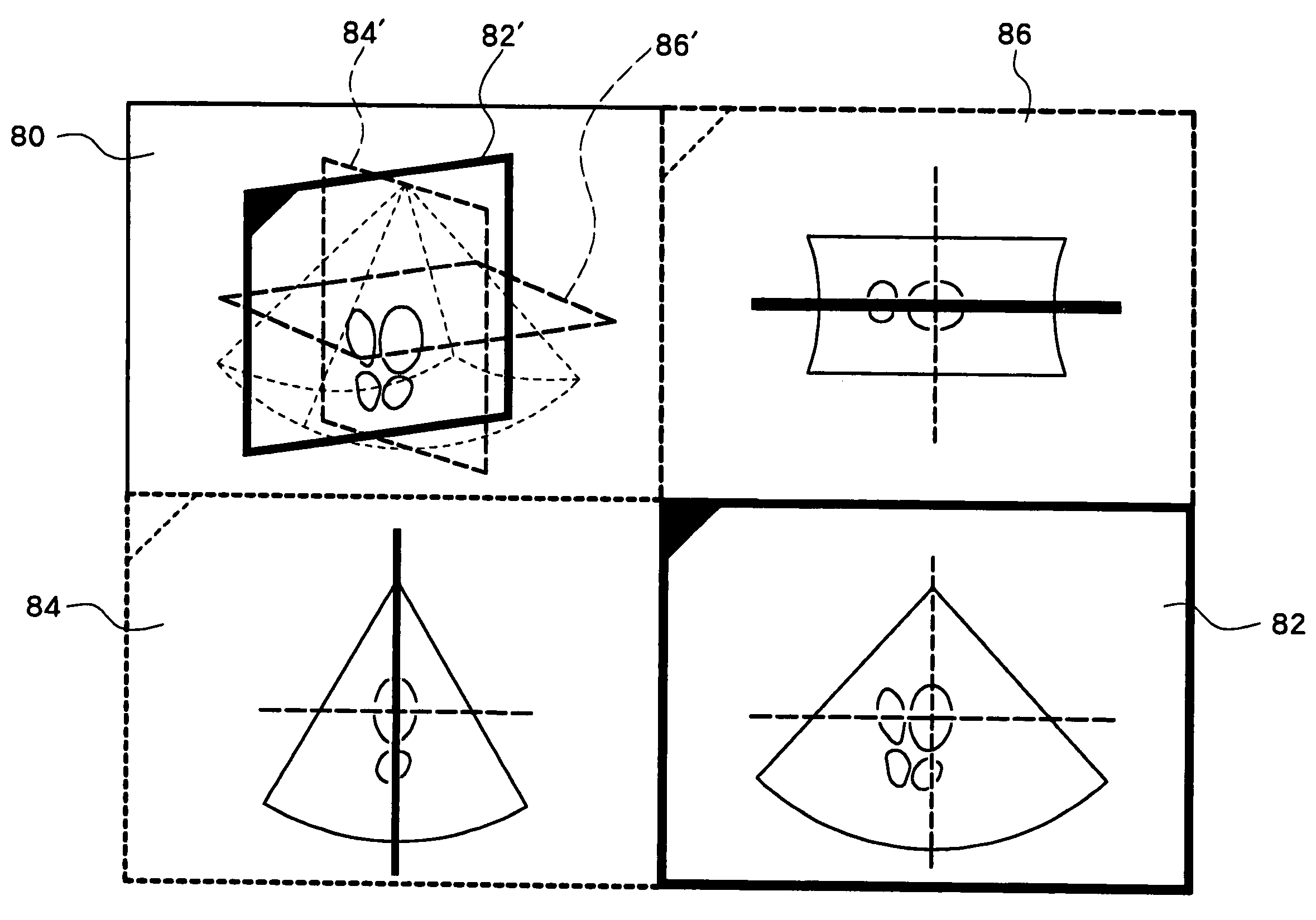
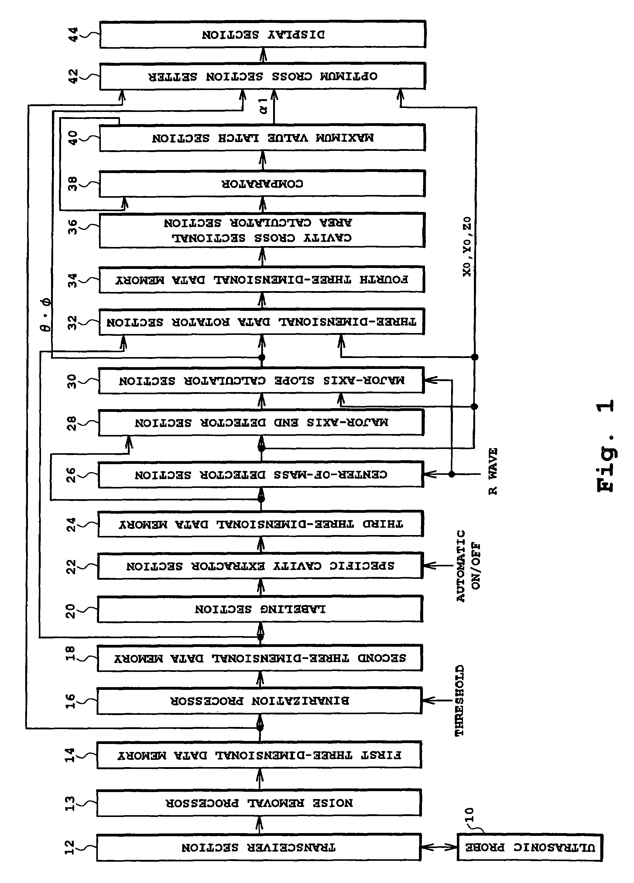
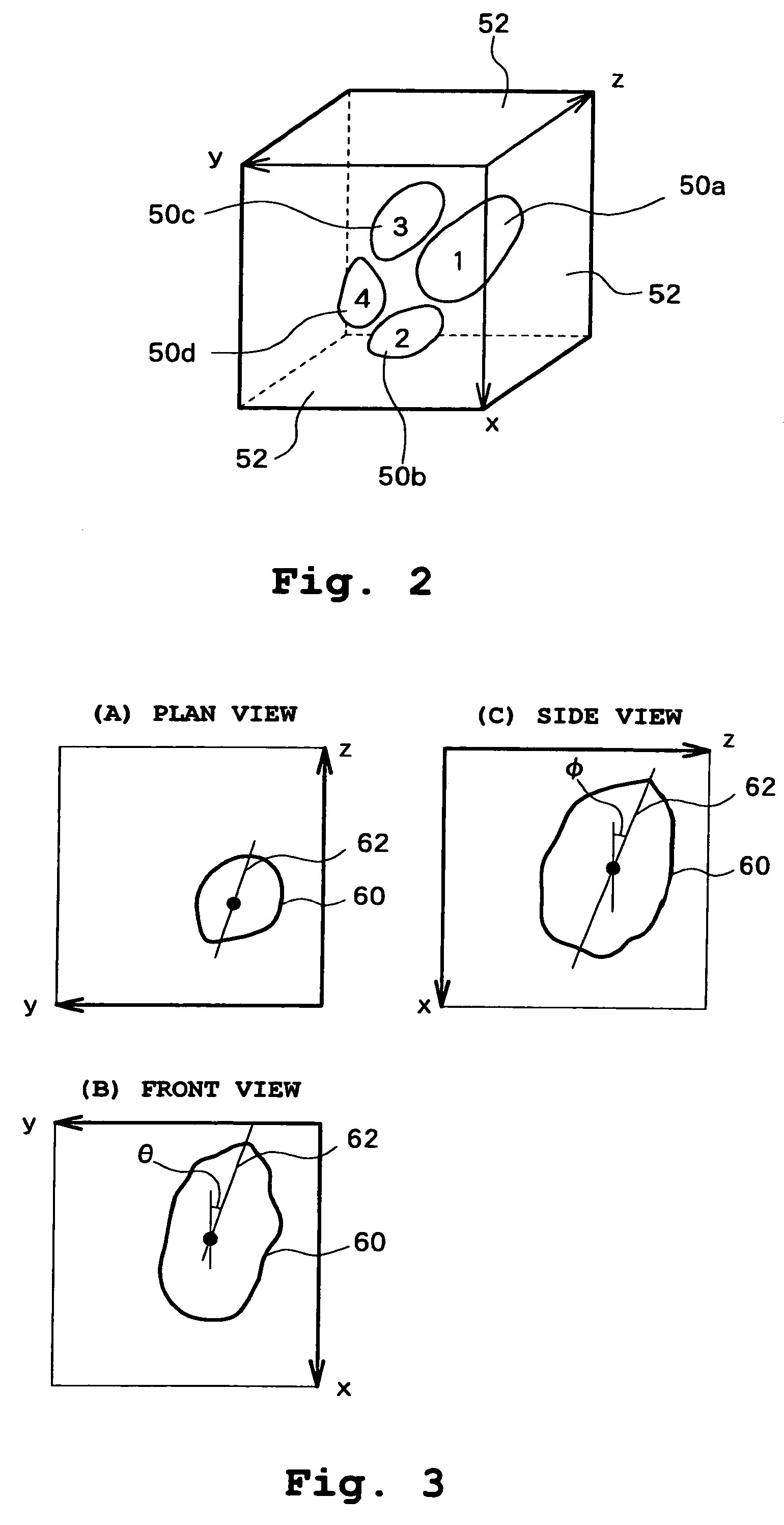
[0026]FIG. 1 is a block diagram showing an overall structure of an ultrasonic diagnostic apparatus according to a preferred embodiment of the present invention. FIGS. 2-5 are diagrams illustrating processes applied in each section of the ultrasonic diagnostic apparatus shown on FIG. 1. An operation of the ultrasonic diagnostic apparatus shown on FIG. 1 will be described referring to FIGS. 2-5.

[0027]An ultrasonic probe 10 is an ultrasonic probe for obtaining three-dimensional echo data. The ultrasonic probe 10 is used in contact with the skin of a patient or is inserted into a body cavity. The ultrasonic probe 10 transmits or receives ultrasound to or from a three-dimensional space by mechanically scanning a 1-D array oscillator which transmits or receives ultrasound to or from a two-dimensional space by electrical scanning. Alternatively, the ultrasonic probe 10 may transmit or rece...


PUM


Abstract

A specific cavity extractor extracts an isolated group corresponding to a left ventricle from among a plurality of isolated groups to which numbers are attached in a labeling section. A major axis slope calculator section sets, as a left ventricle major axis, a straight line passing through a center of mass calculated in a center-of-mass detector section and a major-axis end point detected in a major-axis end detector section. A cavity cross sectional area calculator section calculates a cross sectional area of four cavities for each of a plurality of cutting planes including the left ventricle major-axis. An optimum cross section setter sets, as a four-cavity cross section, a cutting plane in which the cross sectional area of the four cavities becomes maximum.

Description

BACKGROUND OF THE INVENTION[0001]1. Field of the Invention[0002]The present invention relates to an ultrasonic diagnostic apparatus and in particular to a three-dimensional ultrasonic diagnostic apparatus having a function to display an arbitrary cross section.[0003]2. Description of the Related Art[0004]Ultrasonic diagnostic apparatuses are known in which ultrasound is transmitted to / from a three-dimensional space including a target tissue to obtain three-dimensional image data and an arbitrary cross section of the target tissue is displayed based on the three-dimensional image data. For example, Japanese Patent Laid-Open Publication No. 2002-245487 discloses an ultrasonic diagnostic apparatus which displays a synthesized image of a three-dimensional image and an image of an arbitrary cross section, and, at the same time, displays a cross sectional image which is an image of the arbitrary cross section viewed from the front. This type of ultrasonic diagnostic apparatus which has a ...

Claims


Application Information

Patent Timeline
Patent Type & Authority Patents(United States)
IPC IPC(8): A61B8/00A61B8/08G01S7/52G01S15/89G06T1/00G06T7/60
CPCA61B8/08A61B8/0883A61B8/483G01S7/52073G01S7/52074G06T7/602G06T19/00Y10S128/916G06T2207/30048G06T2219/008G06T2219/028G01S15/8993G06T7/62
Inventor MURASHITA, MARASUSETA, AKINORI
Owner HITACHI LTD
Why Eureka
Try Eureka