
Clay-based hemostatic agents and devices for the delivery thereof

a technology of hemostasis and hemostasis agent, which is applied in the direction of extracellular fluid disorder, physical/chemical process catalyst, drug composition, etc., can solve the problems of insufficient immediate availability of equipment and trained personnel, insufficient stanch blood flow, and insufficient hemostasis stablization, so as to facilitate its use as a component, reduce discomfort and/or further injury to patients, and eliminate heat generation

Active Publication Date: 2009-10-20
TELEFLEX LIFE SCI LTD
View PDF115 Cites 60 Cited by
  • Summary
  • Abstract
  • Description
  • Claims
  • Application Information

AI Technical Summary

Benefits of technology

The clay-based agents effectively control bleeding by absorbing blood components, reducing discomfort and tissue damage, and can be easily applied and removed, even in sensitive areas, while minimizing dust and adhesion issues.

Problems solved by technology

Often bleeding is associated with such wounds.
Unfortunately, however, in other circumstances substantial bleeding can occur.
If such aid is not readily available, excessive blood loss can occur.
When bleeding is severe, sometimes the immediate availability of equipment and trained personnel is still insufficient to stanch the flow of blood in a timely manner.
Moreover, severe wounds can often be inflicted in remote areas or in situations, such as on a battlefield, where adequate medical assistance is not immediately available.
Although these materials have been shown to be somewhat successful, they are sometimes not effective enough for traumatic wounds and tend to be expensive.
Furthermore, these materials are sometimes ineffective in some situations and can be difficult to apply as well as remove from a wound.
Additionally, or alternatively, the previously developed materials can produce undesirable side effects.
Oftentimes excess material is unnecessarily poured onto a wound, which can exacerbate the exothermic effects.
Depending upon the specific attributes of the material, the resulting exothermia may be sufficient to cause discomfort to or even burn the patient.
Although some prior art patents specifically recite the resulting exothermia as being a desirable feature that can provide clotting effects to the wound that are similar to cauterization, there exists the possibility that the tissue at and around the wound site may be undesirably impacted.
If an amount of material is administered that causes discomfort or burning, the wound may require immediate flushing.
In instances where a wounded person or animal has not yet been transported to a facility capable of providing the needed irrigation, undesirable effects or over-treatment of the wound may result.
Bleeding can also be a problem during surgical procedures.
However, when the bleeding becomes excessive, these measures may not be sufficient to stop the blood flow.
Moreover, any highly exothermic bleed-control material may damage the tissue surrounding the bleed site and may not be configured for easy removal after use.

Method used


Image

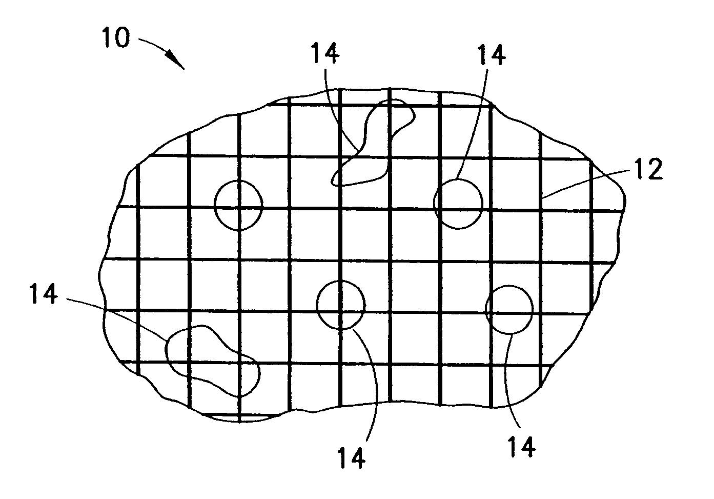
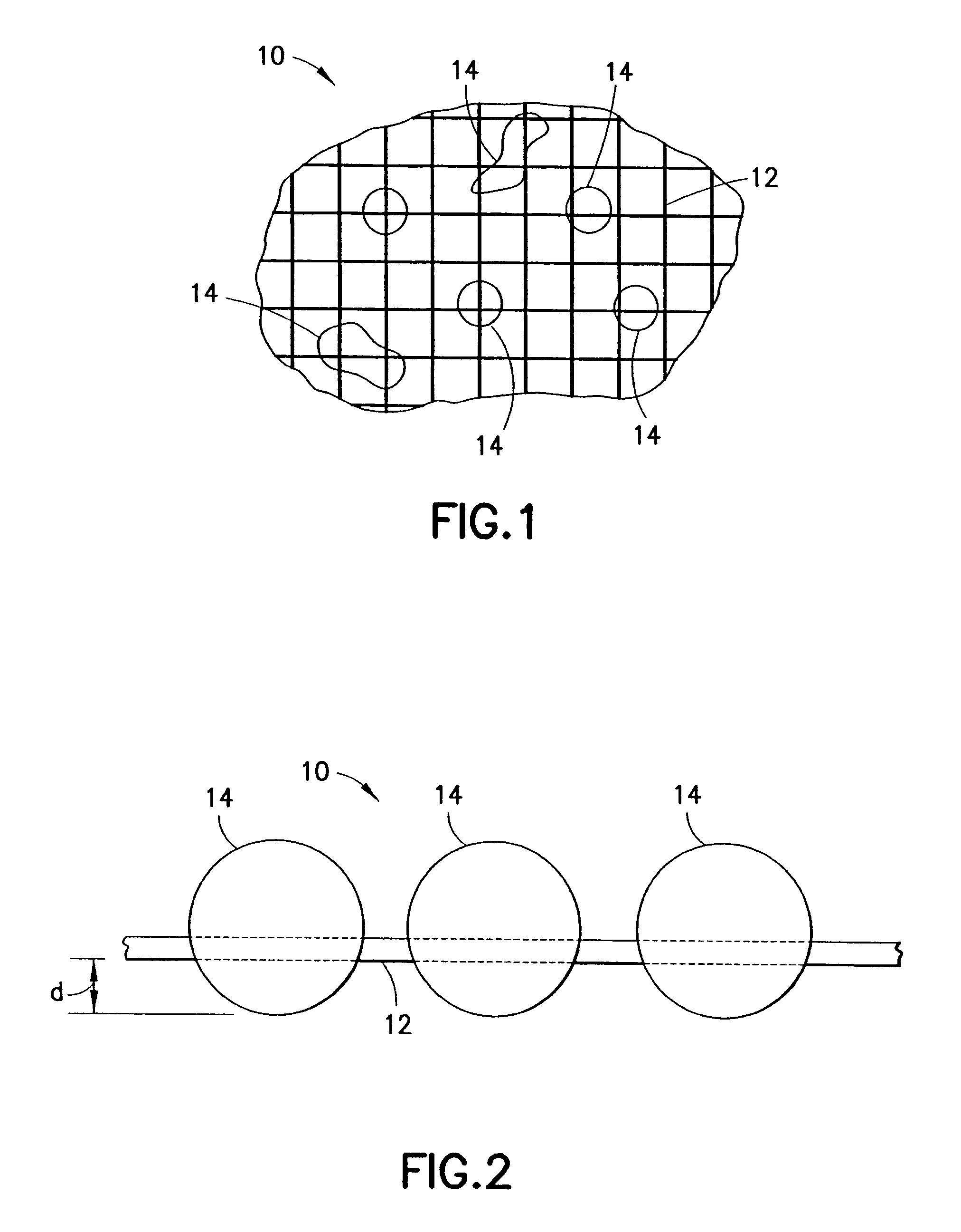
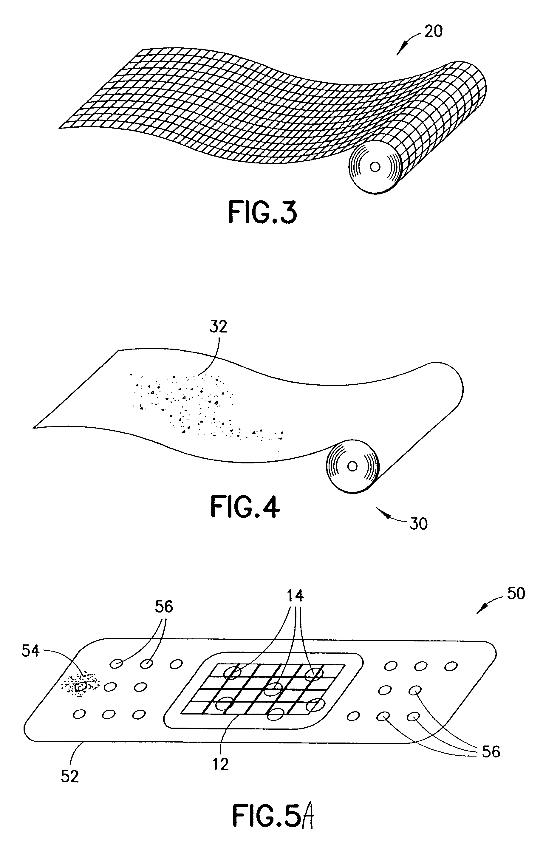
  • Clay-based hemostatic agents and devices for the delivery thereof
  • Clay-based hemostatic agents and devices for the delivery thereof
  • Clay-based hemostatic agents and devices for the delivery thereof

Examples


example 1

The effect of slurry temperature on the ability of cotton gauze to retain kaolin clay

[0085]Temperatures of kaolin / water slurries were varied to assess the ability of cotton gauze to retain kaolin clay. Slurries of water and EPK were prepared in which the kaolin was 40% of the total weight of the slurry. Three sponges were made (one from each piece of gauze) by immersing the cotton gauzes into the slurries of varying temperatures, rolling the wet sponges under pressure, and drying. The Table below indicates the parameters for each slurry and the results obtained.

[0086]

SlurryStartingGauzeTemp.gauzeweight(degreesAgitationweightafter% kaolinSampleC.)method(grams)(grams)(wt. %)122Stir 13.1395.5944minute290Stir 13.0645.86848minute3100Boil 13.0856.48152minute

[0087]The gauze weight after is the weight of the gauze after rolling and drying. It was noted that the elevated slurry temperature increased the amount of retained kaolin. One theory for this is that the cotton fiber structure of the ...

example 2

Application of dry kaolin to dry cotton gauze to form hemostatic device

[0088]Dry kaolin was applied to a dry cotton gauze. The gauze was then rolled. The amount of kaolin retain on the gauze was visibly and significantly less than the amount of kaolin retained on the gauze of Sample 3 (Example 1). This sample, however, accelerated the clot time in sheep whole blood by 70% over the unaccelerated clot time of the blood.

example 3

Reduction of kaolin dust using glycerol

[0089]A slurry of 50 grams (g) of water, 20 g of glycerol, and 15 g of kaolin powder was prepared and used to saturate a gauze sponge (Kendall Curity 2733). The saturated gauze sponge was dried. The sponge was held and tapped with a pencil over a clean glass surface. A visual determination indicated that no readily discernible dust was removed from the sponge as a result of the tapping.

[0090]A second sponge was prepared without glycerol and dried. The second sponge was held and tapped with a pencil over a clean glass surface. A visual determination indicated that a substantial amount of kaolin dust was removed from the second sponge as a result of the tapping.


PUM

PropertyMeasurementUnit
diametersaaaaaaaaaa
diametersaaaaaaaaaa
diametersaaaaaaaaaa

Abstract

A hemostatic device for promoting the clotting of blood includes a gauze substrate, a clay material disposed on the gauze substrate, and also a polyol such as glycerol or the like disposed on the gauze substrate to bind the clay material. When the device is used to treat a bleeding wound, at least a portion of the clay material comes into contact with blood emanating from the wound to cause the clotting. A bandage that can be applied to a bleeding wound to promote the clotting of blood includes a flexible substrate and a gauze substrate mounted thereon. The gauze substrate includes a clay material and a polyol. A hemostatic sponge also includes a gauze substrate and a dispersion of hemostatic material and a polyol on a first surface of the substrate.

Description

REFERENCE TO RELATED APPLICATIONS[0001]This application is a continuation-in-part application of U.S. patent application Ser. No. 11 / 590,427, filed Oct. 30, 2006, entitled “Clay-Based Hemostatic Agents and Devices for the Delivery Thereof,” the contents of which are incorporated herein by reference in their entirety. This application is also related to U.S. Provisional Patent Application Ser. No. 60 / 808,618, filed May 26, 2006, entitled “Blood Clotting Compound”; U.S. Provisional Patent Application Ser. No. 60 / 810,447, filed Jun. 1, 2006, entitled “Hemostatic Device with Oxidized Cellulose Pad”; U.S. patent application Ser. No. 11 / 544,238, filed Oct. 6, 2006, entitled “Hemostatic Compositions and Method of Manufacture”; and U.S. patent application Ser. No. 11 / 584,079, filed Oct. 20, 2006, entitled “Devices and Methods for the Delivery of Hemostatic Agents to Bleeding Wounds”; the contents of all of the above-referenced applications being incorporated herein by reference in their ent...

Claims


Application Information

Patent Timeline
Patent Type & Authority Patents(United States)
IPC IPC(8): A61L15/14A61F13/00A61L15/16A61L15/18A61K9/14
CPCA61L15/18A61L15/425A61F13/00012A61F13/00063A61L2400/04A61L15/28A61L15/42A61L15/44C08L1/02C08L5/04A61P17/02A61P7/04A61F13/01012A61L2300/404A61L2300/406A61L2400/16
Inventor HUEY, RAYMONDLO, DENNYBURNS, DANIEL J.
Owner TELEFLEX LIFE SCI LTD
Learn More