
Apparatus for cooling plasma arc torch nozzles

a technology apparatus, which is applied in the direction of solventing apparatus, manufacturing tools, gas-filled discharge tubes, etc., can solve the problems of reducing the service life of plasma arc torch, affecting the cutting quality, and the failure of vented nozzles to achieve plasma cutting processes requiring greater than 200 amperes, etc., to achieve the effect of maximizing the thermal conducting contact area

Active Publication Date: 2009-10-20
HYPERTHERM INC
View PDF23 Cites 38 Cited by
  • Summary
  • Abstract
  • Description
  • Claims
  • Application Information

AI Technical Summary

Benefits of technology

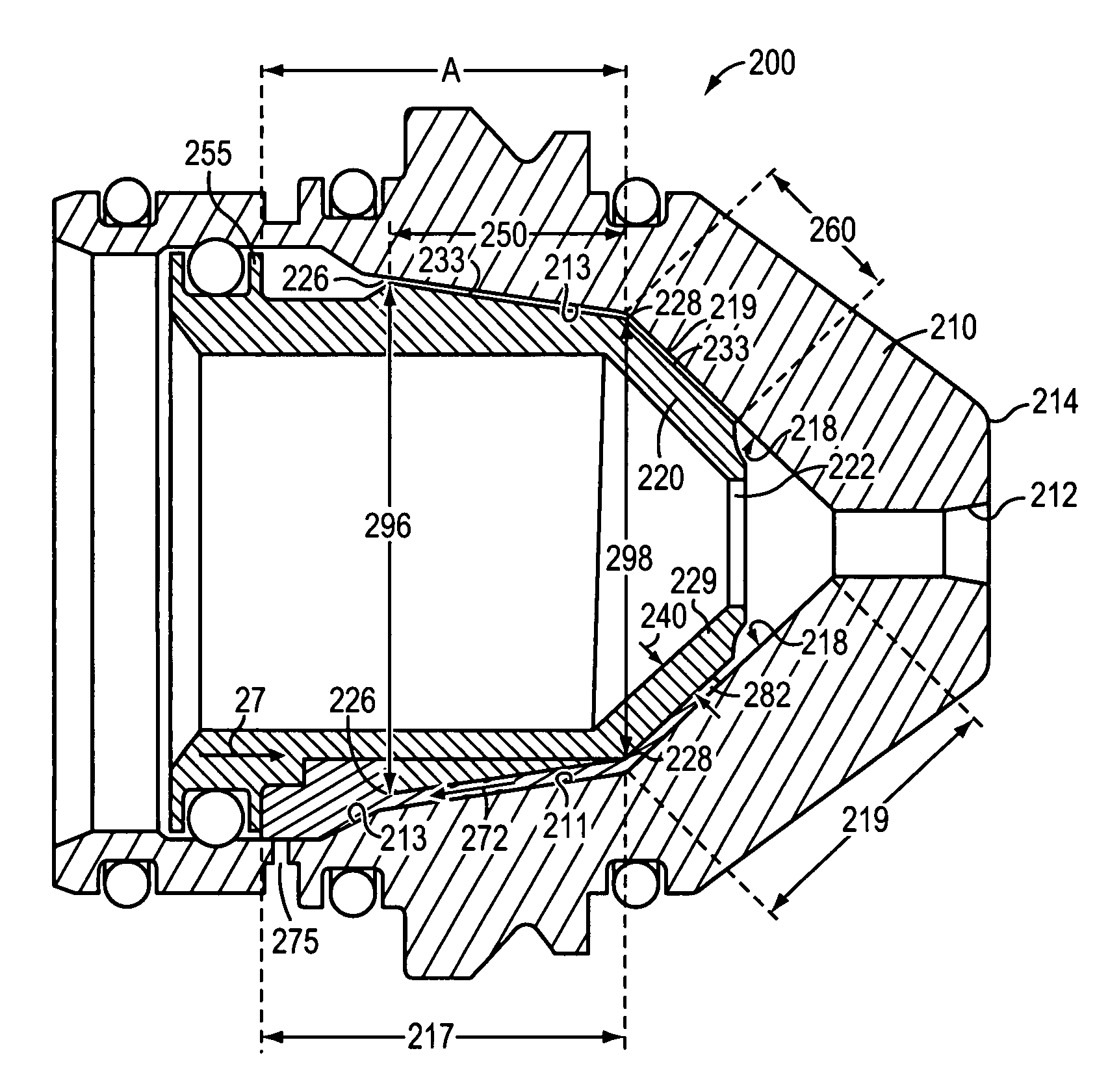
[0006]The improved nozzle overcomes the limitations of prior vented nozzles and can be employed in high current and / or high amperage ranges including torch conditions greater than 200 amperes. The improved nozzle maximizes the thermal conducting contact area between the nozzle liner and the nozzle body, which provides improved cooling of the nozzle liner. The improved nozzle can be used in applications employing greater than 200 amperage.
[0011]In another aspect, the invention relates to a method of manufacturing a nozzle for use in a plasma arc torch. The method includes, providing a nozzle body having a hollow interior and a nozzle exit orifice at a distal end. The nozzle body has a cylindrical portion. The method also includes press fitting a nozzle liner into the hollow interior of the nozzle body to (a) align a liner exit orifice with the nozzle exit orifice, and (b) provide close thermal contact between an exterior surface of a cylindrical section of the nozzle liner with a majority of an interior surface of the cylindrical portion of the nozzle body.

Problems solved by technology

Prior vented nozzles are limited as to the torch conditions that they can withstand.
For example, vented nozzles have not been successfully implemented for plasma cutting processes requiring greater than 200 amperes.
Upon exposure to amperage conditions greater than 200 amperes, prior nozzles become too hot and, as a result, one or more of: an arc fails to form, double arcs form, cut quality suffers, nozzles melt, portions of the nozzle char, and portions of the nozzle become deformed.

Method used


Image

  • Apparatus for cooling plasma arc torch nozzles
  • Apparatus for cooling plasma arc torch nozzles
  • Apparatus for cooling plasma arc torch nozzles

Examples


Embodiment Construction

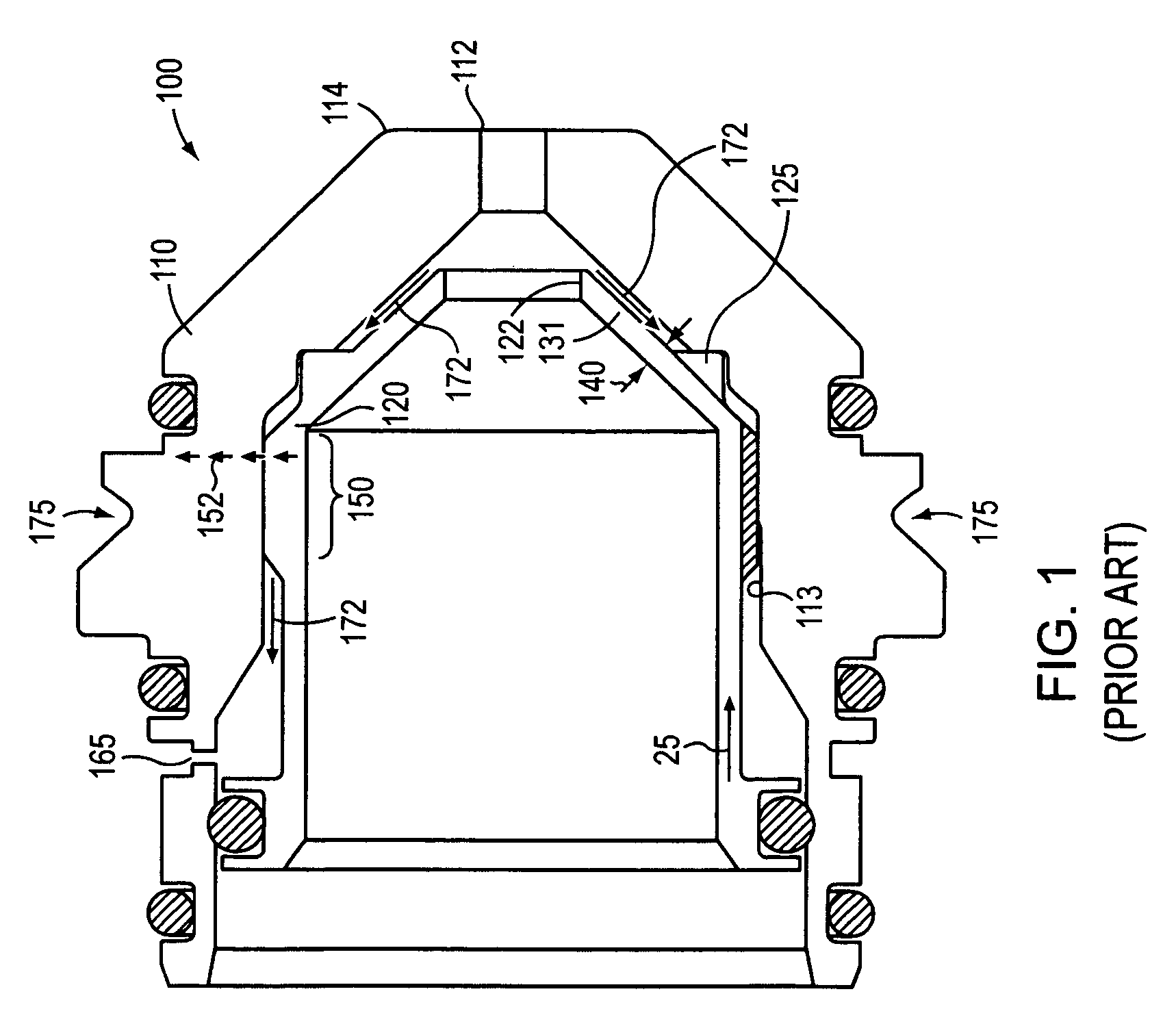
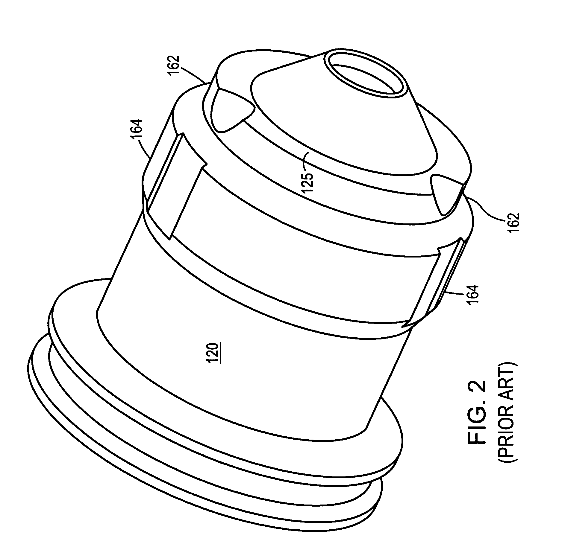
[0025]Prior vented nozzles have not been successfully implemented for plasma cutting processes requiring currents greater than 200 amperes. FIG. 1 shows the cross-section of the HyPerformance® System 200A mild steel nozzle, a vented nozzle available from Hypertherm Inc. (Hanover, N.H.). The nozzle 100 has two pieces, an outside piece called a nozzle body 110 and an inside piece called a nozzle liner 120. A space between the nozzle body interior surface and the exterior surface of the nozzle liner forms a gas flow path 172. A portion of plasma gas is vented from the nozzle 100 via the gas flow path 172 and exits from an aperture in the nozzle body called a vent hole 165 to a vent line and then to the atmosphere. Referring now to FIG. 2, grooves 162, 164 defined on an exterior surface of the nozzle liner 120 enable gas to flow through the gas flow path 172.

[0026]During operation, the nozzle 100 needs to be cooled to prevent heat damage from the high temperature plasma jet. In common i...


PUM


Abstract

The invention relates to a nozzle for a plasma arc torch and methods of manufacturing the nozzle. The nozzle includes a nozzle body and a nozzle liner. The nozzle body has a cylindrical portion and the nozzle liner has a cylindrical section in close thermal contact with a majority of an interior surface of a cylindrical portion of the nozzle body.

Description

RELATED APPLICATIONS[0001]This application claims the benefit of the filing date of U.S. Provisional Patent Application Ser. No. 60 / 672,777, filed on Apr. 19, 2005, entitled “Plasma Arc Torch Providing Angular Shield Flow Injection” by Duan et al., the entirety of which is incorporated herein by reference. This application also claims the benefit of and is a continuation-in-part of U.S. Ser. No. 11 / 407,370, entitled “Plasma Arc Torch Providing Angular Shield Flow Injection” by Duan et al. filed on Apr. 19, 2006, the entirety of which is incorporated herein by reference.FIELD OF THE INVENTION[0002]The invention generally relates to the field of plasma arc torches. In particular, the invention relates to an improved nozzles useful in high amperage ranges of torch operation and a method of manufacturing such nozzles.BACKGROUND OF THE INVENTION[0003]Conventional plasma arc cutting torches produce a transferred plasma jet with current density that is typically in the range of 20,000 to 4...

Claims


Application Information

Patent Timeline
Patent Type & Authority Patents(United States)
IPC IPC(8): H05B1/02
CPCH05H1/34H05H2001/3457H05H2001/3484H05H2001/3478H05H1/3457H05H1/3484H05H1/3478
Inventor DUAN, ZHENG
Owner HYPERTHERM INC
Learn More