Carrier recovery in a coherent optical receiver

a carrier recovery and optical receiver technology, applied in the field of optical communication networks, can solve the problems of preventing successful deployment in “real-world” installed communications networks, significant increase in frequency mismatch beyond this amoun

Active Publication Date: 2009-10-20
CIENA
View PDF21 Cites 131 Cited by
  • Summary
  • Abstract
  • Description
  • Claims
  • Application Information

AI Technical Summary

Problems solved by technology

However, receivers based on coherent detection techniques have suffered disadvantages that have, to date, prevented successful deployment in “real-world” installed communications networks.
Short period phase noise in both of the Tx and LO lasers may significantly increase the frequency mismatch beyond this amount.
This can result in the erroneous interpretation of every symbol (and thus all data) following the cycle-slip.
A limitation of this arrangement is that the analog carrier recovery circuit 12 is an inherently narrow-band device.
Such lasers are very expensive, and thus are not normally used in communications systems.
An additional limitation of Noé's system is that analog circuits are notoriously well known for their inability to adapt to changes following manufacture.
However, a carrier recovery circuit optimized for 10 Gbaud single-polarization signals will not be able to accommodate a polarization-multiplexed 40 GBaud signal.

Method used


Image

  • Carrier recovery in a coherent optical receiver
  • Carrier recovery in a coherent optical receiver
  • Carrier recovery in a coherent optical receiver

Examples


Embodiment Construction

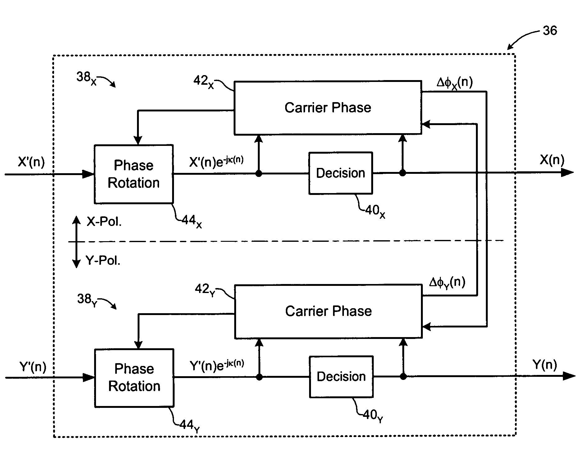
[0030]The present invention provides methods and techniques that enable carrier recovery in a receiver unit of an optical network. Embodiments of the present invention are described below, by way of example only, with reference to FIGS. 2-13b.

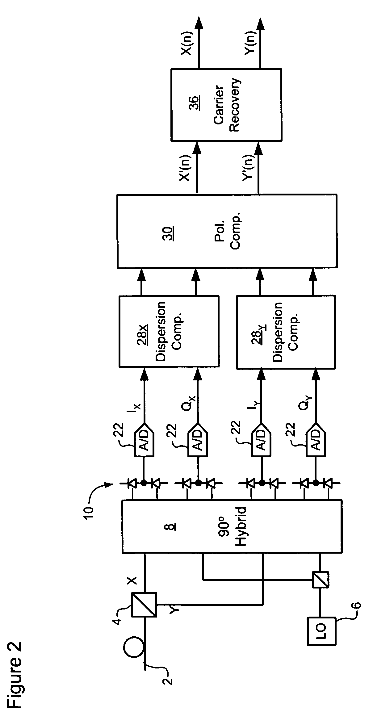
[0031]In general, the present invention provides a system in which carrier recovery is performed in the digital domain, downstream of digital chromatic dispersion and polarization compensation functions. FIG. 2 schematically illustrates a representative coherent optical receiver in which digital carrier recovery can be employed.

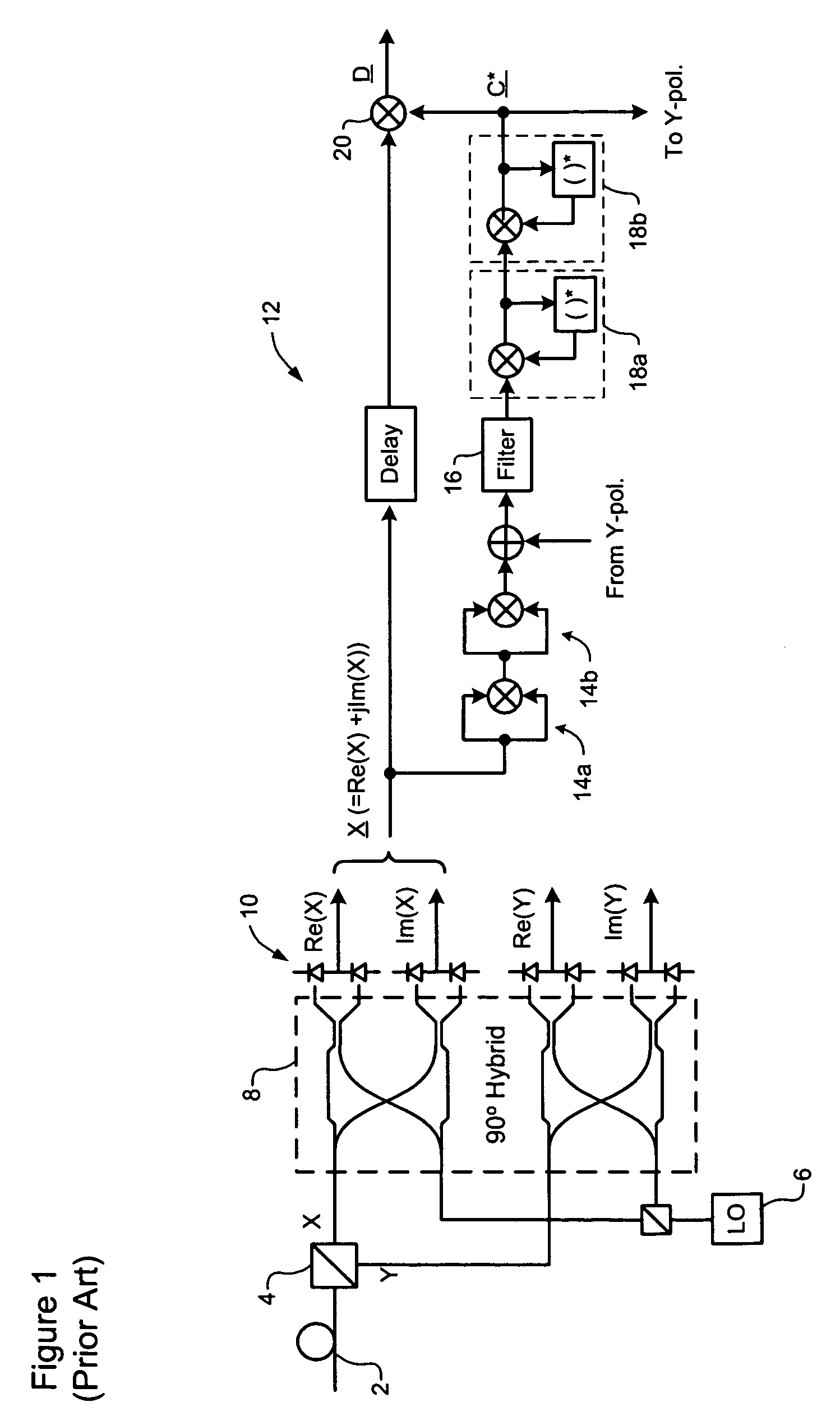
[0032]In the coherent optical receiver of FIG. 2, an inbound optical signal is received through an optical link 2, split into orthogonal polarizations by a Polarization Beam Splitter 4, and then mixed with a Local Oscillator (LO) signal 6 by a conventional 90° hybrid 8. The composite optical signals emerging from the optical hybrid 8 are supplied to respective photodetectors 10, which generate corresponding analog signa...


PUM


Abstract

A method of carrier recovery from a high speed optical signal received through an optical communications network. A stream of multi-bit digital samples of the optical signal is processed to generate a multi-bit estimate X′(n) of each one of a plurality of transmitted symbols. A phase of each symbol estimate X′(n) is rotated, and a respective symbol phase error Δφ(n) of the rotated symbol estimate determined.

Description

CROSS-REFERENCE TO RELATED APPLICATIONS[0001]This application claims benefit under 35 U.S.C. 119(e) from U.S. Provisional Patent Application Ser. No. 60 / 728,751, entitled Automatic Gain Control, which was filed on Oct. 21, 2005.TECHNICAL FIELD[0002]The present invention relates to optical communications networks, and in particular to methods and systems for carrier recovery in a coherent optical receiver.BACKGROUND OF THE INVENTION[0003]In the optical communications space, techniques used to detect data modulated onto an optical signal may be broadly grouped into two classes, namely “direct” detection and “coherent” detection. In “direct” detection techniques, the optical signal is made incident on a photodetector. The electrical current appearing at the photodetector output is proportional to the optical power. Data modulated onto the optical signal power using an amplitude-modulation scheme, such as On-Off Keying (OOK) can thus be detected by analysis of the photodetector output c...

Claims


Application Information

Patent Timeline
Patent Type & Authority Patents(United States)
IPC IPC(8): H04B10/00
CPCH04B10/60H04B10/61H04L7/0075H04B10/6165H04B10/6162H04L7/0004
Inventor WU, KUANG TSANSUN, HANROBERTS, KIM B.JIN, RUIBINHARLEY, JAMES
Owner CIENA
Why Eureka
Try Eureka