Semiconductor device and manufacturing method thereof
a semiconductor and film technology, applied in the field of semiconductor devices, can solve the problems of thermal oxidation difficult to be performed, leakage current or short between, defects in the film, etc., and achieve the effects of improving and stabilizing the characteristics of semiconductor elements such as transistors, reducing light intensity, and increasing the density of wires
- Summary
- Abstract
- Description
- Claims
- Application Information
AI Technical Summary
Benefits of technology
Problems solved by technology
Method used
Image
Examples
embodiment mode 1
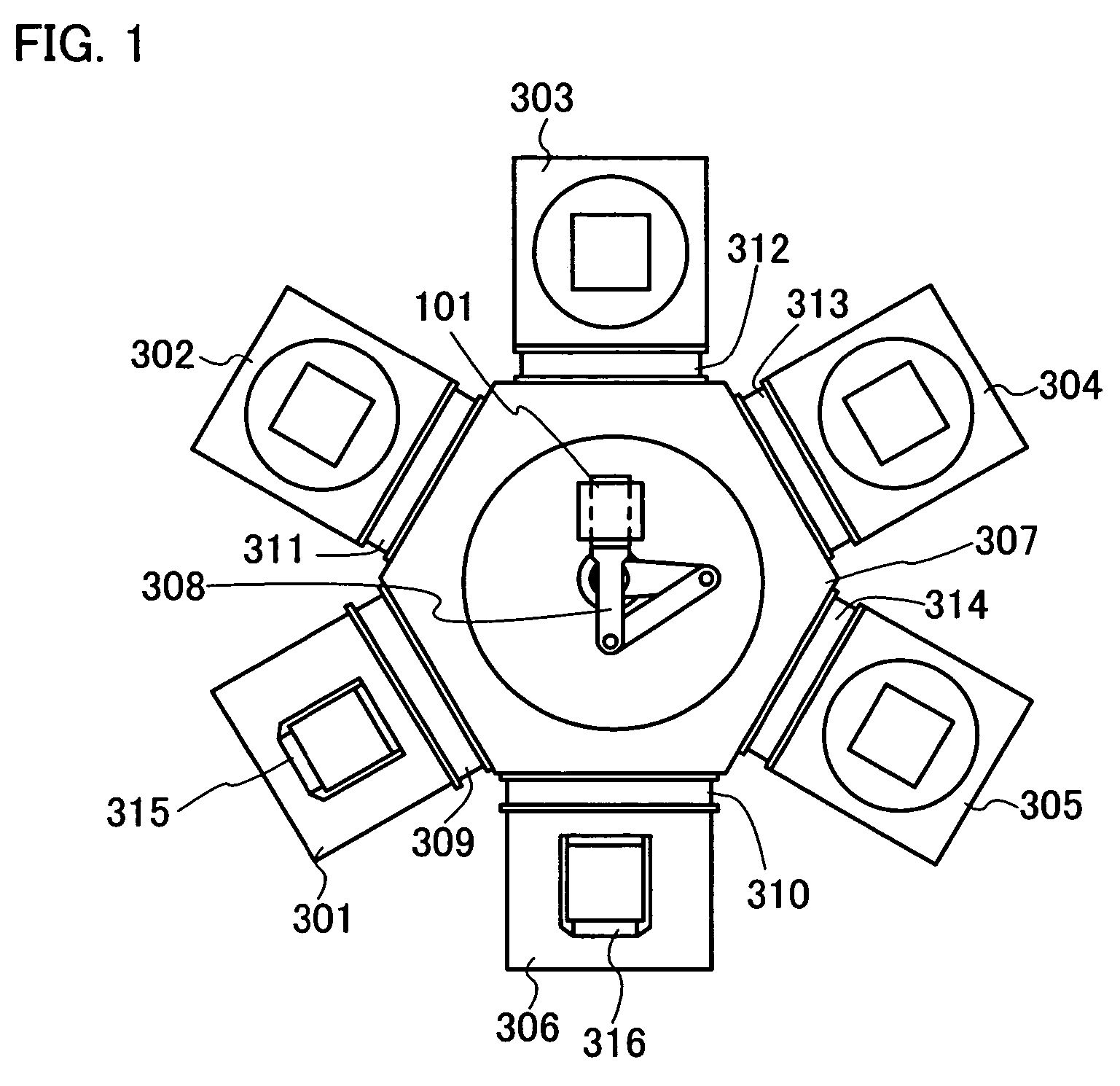
[0051]FIG. 1 illustrates an exemplary plasma treatment apparatus in accordance with the manufacture of a semiconductor device. The plasma treatment apparatus shown in FIG. 1 has a plurality of treatment chambers capable of generating plasma, a common chamber for transferring substrates to each chamber, and a load lock chamber for taking in or out the substrates. Thus, in the case of continuously performing deposition of an insulating film, a conductive layer, or a semiconductor layer and plasma treatment thereof, a plasma treatment apparatus having a plurality of treatment chambers can be used. Note that FIG. 1 is a top plan view showing one exemplary structure of a plasma treatment apparatus shown in this embodiment mode.
[0052]The plasma treatment chamber shown as an illustrative example in FIG. 1 includes a first treatment chamber 302, a second treatment chamber 303, a third treatment chamber 304, a fourth treatment chamber 305, load lock chambers 301 and 306, and a common chamber...
embodiment mode 2
[0072]A silicon oxide film which is deposited by plasma CVD with a parallel-plate chamber in which plasma is excited with a frequency of typically 13.56 MHz has a possibility that many defects are produced in the film due to the plasma damage or unreacted gas species during the film deposition. When transistors are manufactured by using such a silicon oxide film, various characteristics such as the threshold voltage or electron field-effect mobility are adversely affected.
[0073]First, as shown in FIG. 4A, a silicon nitride film is formed with a thickness of 50 to 100 nm as a base insulating layer 102 over a substrate 101, by sputtering, low-pressure CVD, or plasma CVD. The silicon nitride film as the base insulating layer 102 is deposited at a substrate temperature of 250 to 400° C., or preferably 300 to 350° C. by supplying a gas of SiH4 and NH3 and / or N2. In this case, a silicon oxynitride film may be used instead of the silicon nitride film. The silicon oxynitride film can be for...
embodiment mode 3
[0082]An insulating layer formed between a glass substrate and a semiconductor layer in order to form a crystalline semiconductor layer is provided for the purpose of preventing diffusion of impurities from the substrate into the semiconductor layer as well as planarizing the surface of the glass substrate. Although a silicon nitride film is suitable for a blocking film which serves to prevent diffusion of impurities, it cannot be formed thick because of its high internal stress, so that it cannot increase the planarizing effect. In this embodiment mode, description will be made of an example of forming a base film by effectively using high-density plasma treatment, with reference to FIGS. 5A to 5E.
[0083]First, a substrate 101 is prepared, and the surface of the substrate 101 is cleaned with hydrofluoric acid (HF), alkali or pure water. The substrate 101 may be a glass substrate such as barium borosilicate glass, alumino borosilicate glass, or aluminosilicate glass, a quartz substra...
PUM
 Abstract
Description
Claims
Application Information
 - R&D
- Intellectual Property
- Life Sciences
- Materials
- Tech Scout
- Unparalleled Data Quality
- Higher Quality Content
- 60% Fewer Hallucinations
Browse by: Latest US Patents, China's latest patents, Technical Efficacy Thesaurus, Application Domain, Technology Topic, Popular Technical Reports.
© 2025 PatSnap. All rights reserved.Legal|Privacy policy|Modern Slavery Act Transparency Statement|Sitemap|About US| Contact US: help@patsnap.com


