Process for production of propylene and ethylbenzene from dilute ethylene streams

a technology of ethylene and benzene, which is applied in the field of production of ethylbenzene and propylene, can solve the problems of inefficient recycle step, inconvenient recycling of ethylene, and energy penalty for fixed-bed processes, and achieves significant energy and consequently cost, and eliminates the ethylene recycle step

Inactive Publication Date: 2009-10-27
LUMMUS TECH INC
View PDF20 Cites 7 Cited by
  • Summary
  • Abstract
  • Description
  • Claims
  • Application Information

AI Technical Summary

Benefits of technology

[0017]The advantages of the invention include significant energy, and consequently cost, savings by eliminating or reducing the final fractionation of ethylene in the ethylene plant and by eliminating the ethylene recycle step in the propylene plant.

Problems solved by technology

Dilute ethylene from an ethane cracker may have relatively low amounts of methane and hydrogen, but this may not always be the case since, for example, dilute ethylene from an ethylene plant with a front-end deethanizer may contain larger quantities of hydrogen and methane.
In any event, fixed-bed processes will incur an energy penalty when the ethylene feed purity is below about 83 mol %.
The energy penalty includes additional energy which must be used in the ethylbenzene plant when ethylene sources used are very dilute.
Unfortunately, an ethylene feed which is more dilute than about 95 mol %, will result in a very inefficient recycle step, which comprises heating, cooling and fractionation of the unreacted dilute ethylene, because after an initial reaction with butenes the unreacted ethylene is generally diluted by relatively high levels of ethane and / or other light gases which build up in the recycle step.
The result is that it is more difficult and more costly to recover ethylene in the recycle step and, thus, it may be more efficient to simply purge significant amounts of ethylene from the process along with the light gases rather than returning the ethylene to the reactor.
Consequently, when a dilute ethylene feed is used, ethylene left over after the initial reaction with the butenes would be essentially unusable and not worth the energy cost of the recycle step.
Although the unreacted ethylene could be returned to the ethylene plant for recovery, this would be very costly.

Method used


Image

  • Process for production of propylene and ethylbenzene from dilute ethylene streams
  • Process for production of propylene and ethylbenzene from dilute ethylene streams
  • Process for production of propylene and ethylbenzene from dilute ethylene streams

Examples


example 1

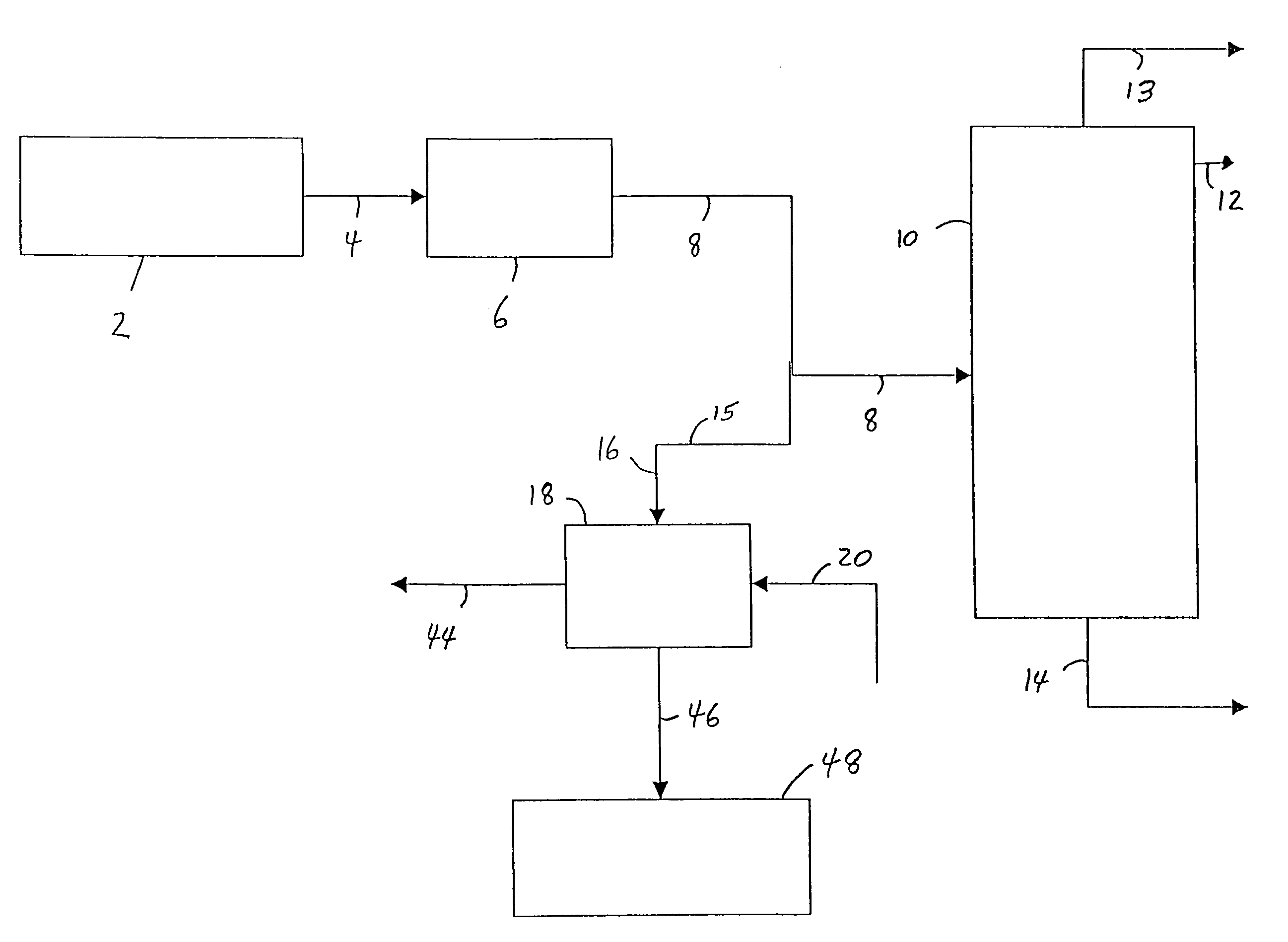
[0032]Referring to FIG. 1, an ethylene plant (up to and including the deethanizer step) 2, produces a vapor stream, comprising ethylene, ethane and acetylene, and may also comprise, e.g., unreacted hydrogen, methane and propylene, is sent via line 4 to an acetylene removal process 6 which is commonly a multiple-stage fixed-bed reactor system using precious metal catalyst. The resulting vapor stream is then sent via line 8 to an ethylene fractionation column 10, wherein the dilute ethylene stream is fractionated into high purity ethylene, which is taken off as overhead from the ethylene fractionation column 10 via line 12; a recycle ethane stream which is taken off as bottoms from the ethylene fractionation column 10 via line 14 (and may later be used to produce more ethylene); and a vent of, e.g., methane and hydrogen, which is taken off as overhead from the fractionation column 10 via line 13, according to known processes. In a preferred process of the invention, at least some of t...

examples 2-5

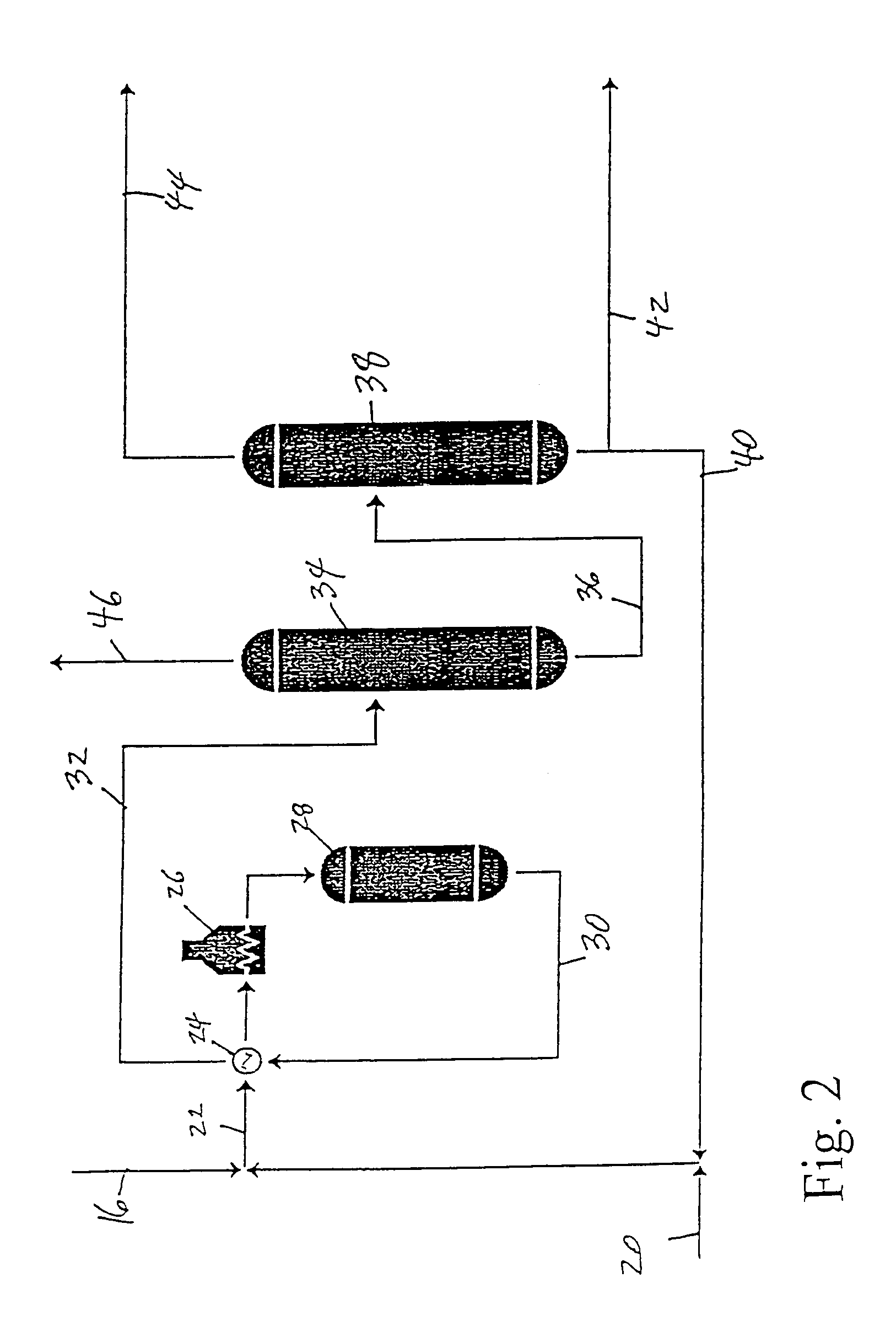
[0037]Examples 2, 3, 4 and 5 show embodiments of the invention which may be practiced in a manner which is very similar to the processes described in Example 1. However, the manner in which the ethylene stream in line 8 is treated before being fed to the propylene plant 18 varies with each example. Consequently, the composition of the feed sent to the propylene plant 18 and to the ethylbenzene plant 48 will also vary for each example.

example 2

[0038]Referring to FIG. 3, the ethylene stream from the ethylene plant 2 is sent, after the acetylene removal process 6, to a condenser 50 wherein the stream is partially condensed to provide liquid feed to the propylene plant 18, via line 52, and vapor feed to the ethylene fractionation column 10, via line 54. The stream in line 54 is vapor with an ethylene concentration of about 1 mol % to about 3 mol % higher than the stream fed to the condenser 50. The liquid stream in line 52 has an ethylene concentration which is about 1 mol % to about 3 mol % lower than the feed in line 8, and is sent to line 16 and on to the propylene plant 18. After reaction in the propylene plant, the remaining ethylene is taken from the deethylenizer 34 (FIG. 2) and sent via line 46 directly to the ethylbenzene plant 48, as in Example 1. Because the ethylene in the feed to the propylene plant is present in excess above that needed for propylene production (the ethylene quantity includes both propylene pro...


PUM

PropertyMeasurementUnit
mol %aaaaaaaaaa
mol %aaaaaaaaaa
mole ratioaaaaaaaaaa

Abstract

A process for producing propylene is provided which includes directing an ethylene stream from an ethylene reaction zone to a propylene reaction zone; directing a butene stream to the propylene reaction zone; reacting the ethylene stream with the butene stream in the propylene reaction zone to produce a propylene reaction stream; and subjecting the propylene reaction stream to a recovery operation to recover propylene. A processes is also provided for producing an alkylaromatic by directing an ethylene stream from a propylene reaction zone to an alkylaromatic reaction zone; directing an aromatic stream to the alkylaromatic reaction zone; reacting the ethylene stream with the aromatic stream in the alkylaromatic reaction zone to produce an alkylaromatic reaction stream; and subjecting the alkylaromatic reaction stream to a recovery operation to recover alkylaromatics. A process for producing propylene and an alkylaromatic is also provided.

Description

CROSS REFERENCE TO RELATED APPLICATIONS[0001]The present application is a Continuation of U.S. application Ser. No. 10 / 458,954 filed Jun. 11, 2003 now abandoned, which is herein incorporated by reference.BACKGROUND OF THE INVENTION[0002]1. Field of the Invention[0003]The invention relates to processes related to the production of ethylbenzene and propylene, particularly to processes related to the production of ethylbenzene and propylene from dilute sources of ethylene.[0004]2. Description of the Related Art[0005]Ethylene is common chemical which may be, among other things, reacted with aromatics to produce alkylaromatics, such as ethylbenzene, and with butenes to produce propylene. Ethylbenzene is commonly used to produce styrene, which may be polymerized to produce polystyrene. Propylene is commonly used for the manufacture of polypropylene.[0006]The process for producing high purity ethylene is well known, and involves pyrolysis of a hydrocarbon feed and subsequent separation of ...

Claims


Application Information

Patent Timeline
Patent Type & Authority Patents(United States)
IPC IPC(8): C07C4/04C07C15/073C07C6/02C07C2/66C07C6/00C07C6/04C07C11/06C10G57/00
CPCC07C2/66C07C6/00C07C6/04C07C11/06C07C15/073C10G2400/20C10G2400/30Y02P20/10C07C7/20
Inventor HILDRETH, JAMES M.DUKANDAR, KERMAN NARIMANVENNER, RONALD M.
Owner LUMMUS TECH INC
Why Eureka
Try Eureka