Fan system and control device thereof

a technology of control device and fan system, which is applied in the direction of motor/generator/converter stopper, dynamo-electric converter control, instrumentation, etc., to achieve the effect of enhancing reliability and use efficiency protecting the overall operation of the fan system, and enhancing the reliability of the fan system

Active Publication Date: 2009-10-27
DELTA ELECTRONICS INC
View PDF6 Cites 17 Cited by
  • Summary
  • Abstract
  • Description
  • Claims
  • Application Information

AI Technical Summary

Benefits of technology

[0014]As mentioned above, in the fan system and the control device thereof according to the invention, a temperature sensing module of the control device can sense an external temperature to generate a sensing signal, a comparing module compares the sensing signal with its reference voltage signal and then outputs a comparing signal, and a driving module controls a rotation speed of a motor according to the sensing signal or the comparing signal. Compared with the prior art, the reference voltage signal and the sensing signal are compared with each other so that it is possible to judge whether the fan system is in the normal state in the fan system and its control device according to the invention. In addition, when the reference voltage signal is lower than the sensing signal, which is an abnormal state of the fan system, a rotating speed control signal for making the motor rotate at the full speed is generated. This method not only uses the comparing module to compare the reference voltage signal with the sensing signal to judge whether the fan system is in the normal state, but also controls the motor to rotate at the full speed when the fan system is in the abnormal state. Thus, the overall operation of the fan system can be protected, and the reliability and the use efficiency of the fan system can be enhanced.

Problems solved by technology

In addition, when the reference voltage signal is lower than the sensing signal, which is an abnormal state of the fan system, a rotating speed control signal for making the motor rotate at the full speed is generated.

Method used


Image

  • Fan system and control device thereof
  • Fan system and control device thereof
  • Fan system and control device thereof

Examples


Embodiment Construction

[0020]The present invention will be apparent from the following detailed description, which proceeds with reference to the accompanying drawings, wherein the same references relate to the same elements.

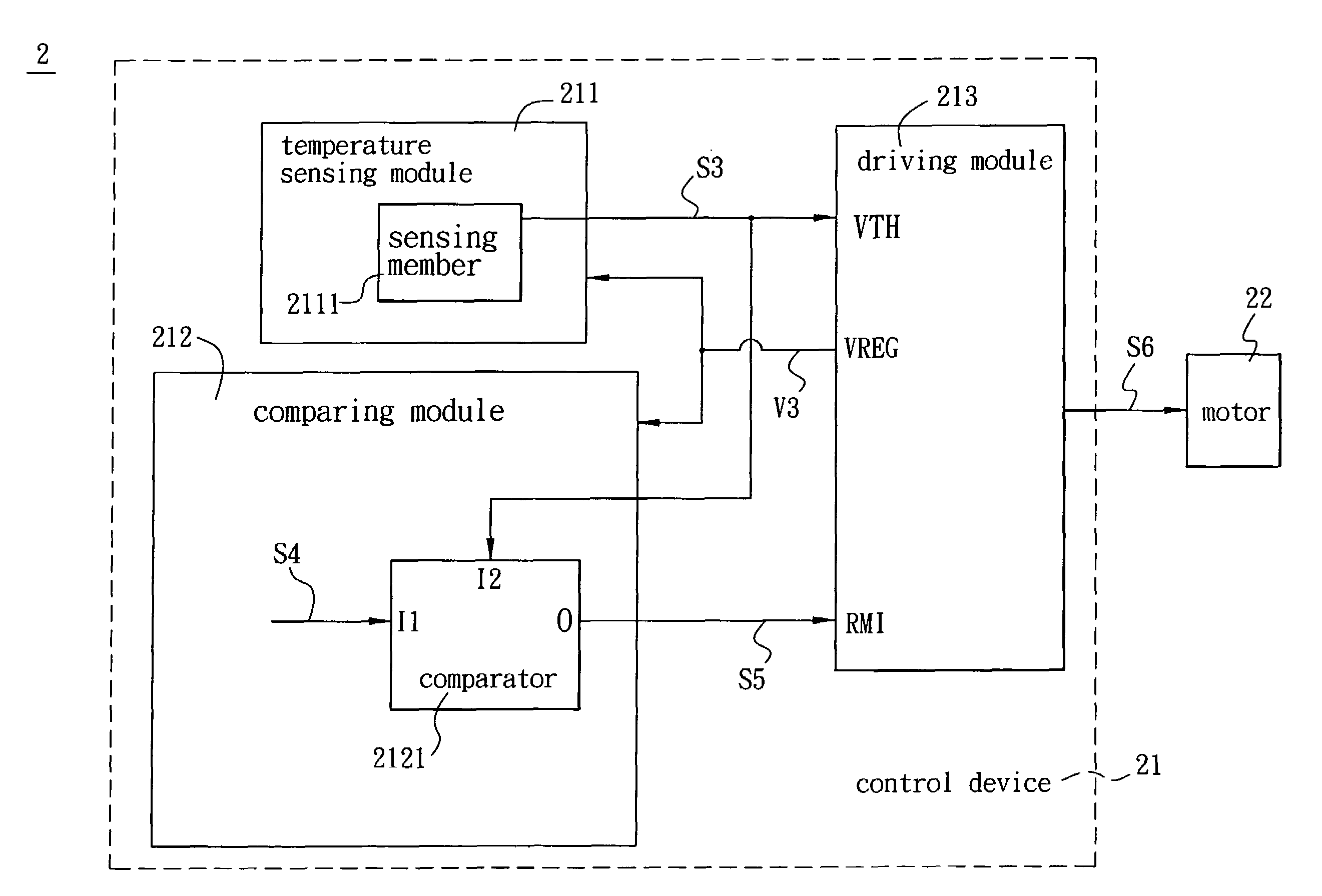
[0021]Referring to FIG. 3, a fan system 2 according to an embodiment of the invention includes a control device 21 and a motor 22. In this embodiment, the control device 21 has a temperature sensing module 211, a comparing module 212 and a driving module 213.

[0022]The temperature sensing module 211 has a sensing member 2111 for sensing an external temperature and generating a sensing signal S3 according to the external temperature. The sensing member 2111 is, for example but not limited to, a thermister in practice. Herein, the sensing member 2111 is a negative temperature coefficient (NTC) thermister, for example. In addition, the sensing signal S3 is, for example but not limited to, a voltage value.

[0023]The comparing module 212 has a comparator 2121, which is electrically connected...


PUM


Abstract

A control device of a fan system includes a temperature sensing module, a comparing module and a driving module. The temperature sensing module senses an external temperature and generates a sensing signal according to the external temperature. The comparing module receives the sensing signal and outputs a comparing signal according to the sensing signal and a reference voltage signal. The driving module, which is electrically connected with the temperature sensing module and the comparing module, supplies a working voltage to the temperature sensing module and the comparing module, and outputs a rotating speed control signal according to the sensing signal or the comparing signal.

Description

CROSS REFERENCE TO RELATED APPLICATIONS[0001]This Non-provisional application claims priority under 35 U.S.C. §119(a) on Patent Application No. 095135070 filed in Taiwan, Republic of China on Sep. 22, 2006, the entire contents of which are hereby incorporated by reference.BACKGROUND OF THE INVENTION[0002]1. Field of Invention[0003]The invention relates to a system and a control device thereof, and in particular, to a fan system and a control device thereof.[0004]2. Related Art[0005]Because the performance and the processing speed of electronic devices are increased and the integration of the used electronic components is increased, the requirement in heat dissipation is greatly increasing. In one solution, a fan is installed in the electronic device to dissipate the heat. A control device of the fan adjusts the rotating speed of the fan according to the environment temperature. The environment temperature is usually sensed by a temperature sensing member, such as a thermister. The t...

Claims


Application Information

Patent Timeline
Patent Type & Authority Patents(United States)
IPC IPC(8): G05D23/00
CPCH05K7/20209G06F1/206Y10S388/934
Inventor LIN, YU-LIANGHSIEH, TSUNG-JUNGHUANG, YUEH-LUNGTSAI, MING-SHI
Owner DELTA ELECTRONICS INC
Why Eureka
Try Eureka