Method for minimizing the tongue and groove effect in intensity modulated radiation delivery

a radiation delivery and intensity modulation technology, applied in radiation therapy, diaphragm/collimeter handling, therapy, etc., can solve the problems of interleaf leakage, striping in the final delivered fluence, striping in the imrt delivery, etc., to reduce and minimize the effect of interleaf leakag

Active Publication Date: 2009-10-27
VARIAN MEDICAL SYST INT AG
View PDF5 Cites 44 Cited by
  • Summary
  • Abstract
  • Description
  • Claims
  • Application Information

AI Technical Summary

Benefits of technology

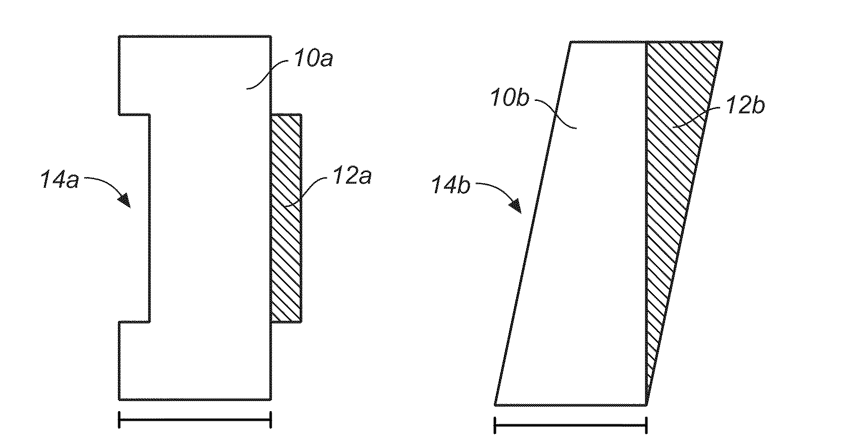
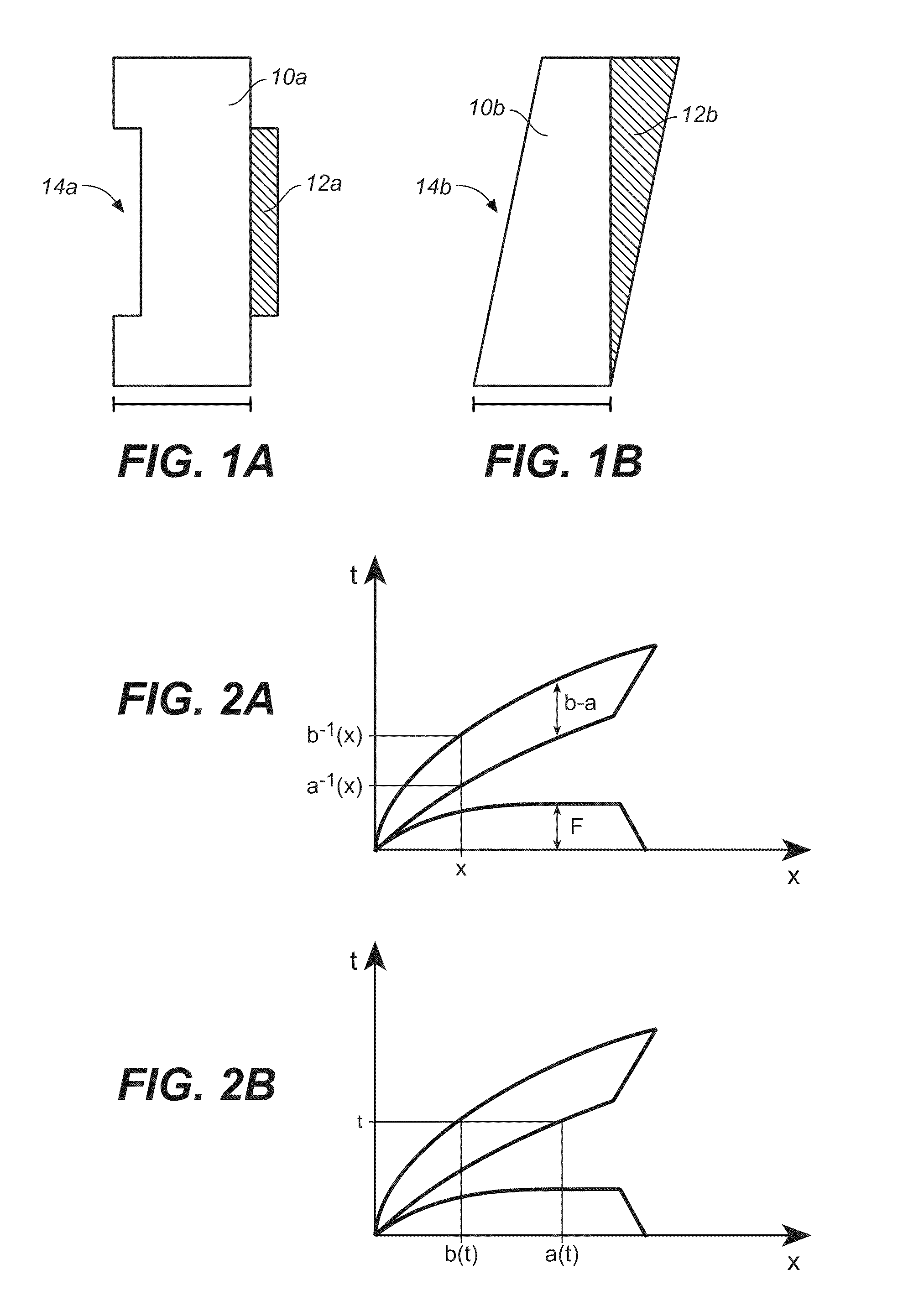
[0006]Although the leaves are positioned closely together, many MLCs have a problem with inter-leaf leakage, where radiation leaks through the space between the leaves. This leakage causes striping in the final delivered fluence, which is undesirable because it causes a variance between the delivered dose and the dose prescribed under the treatment plan. To minimize this inter-leaf leakage, some MLC models use leaves 10a with a tongue 12a and groove 14a design (see FIG. 1A). The tongue of each leaf fits into the groove of the adjacent leaf, blocking radiation from leaking between the leaves and, thereby, reducing striping in the final fluence delivery. Unfortunately, the tongue and groove design can also have the opposite effect; increasing the stripe patterns in the final fluence. This increase occurs when a tongue of one leaf is exposed, i.e., not positioned within the groove of another leaf, during delivery of radiation. The exposed tongue partially blocks radiation from passing, which causes a stripe in the final fluence.
[0007]Throughout this disclosure, the “tongue and groove effect” specifically refers to the negative effect in IMRT delivery that is caused by a thickness of leaf material on the side of a leaf exposed to the incident rays of the radiation beam that is less than the full thickness of the leaf. This thickness can be in the form of an exposed tongue, such as 12a in FIG. 1A, or an exposed groove, such as 14a, but is not limited to this type of leaf design. An “exposed” groove can be thought of as missing material to make room for an adjacent tongue with the remaining leaf material exposed to rays of the beam alone. Exposure of either a tongue or a groove can cause striping in the IMRT delivery. Depending on the geometry of the MLC, the striping caused by an exposed groove may be less significant than that caused by an exposed tongue (such as the leaf design in FIG. 1A), although in most current designs the effect from an exposed tongue is very similar to, if not the same as, the effect from an exposed groove.
[0008]The tongue and groove pattern can be at any height along the leaf side and need not be in the form of a centrally located groove 14a as shown in FIG. 1A. Some MLC designs employ a single stepped side wherein the tongue is a protrusion in one half of the leaf while the “groove” is a mating inset. Other MLC designs use a more symmetrical, slanted leaf pattern (e.g., 10b in FIG. 1B), where the effects of an expose

Problems solved by technology

Rarely, however, can the system jaws alone be used implement a suitable treatment plan.
Although the leaves are positioned closely together, many MLCs have a problem with inter-leaf leakage, where radiation leaks through the space between the leaves.
This leakage causes striping in the final delivered fluence, which is undesirable because it causes a variance between the delivered dose and the dose prescribed under the treatment plan.
Unfortunately, the tongue and groove design can also have the opposite effect; increasing the stripe patterns in the final fluence.
Exposure of either a t

Method used


Image

  • Method for minimizing the tongue and groove effect in intensity modulated radiation delivery
  • Method for minimizing the tongue and groove effect in intensity modulated radiation delivery
  • Method for minimizing the tongue and groove effect in intensity modulated radiation delivery

Examples


example

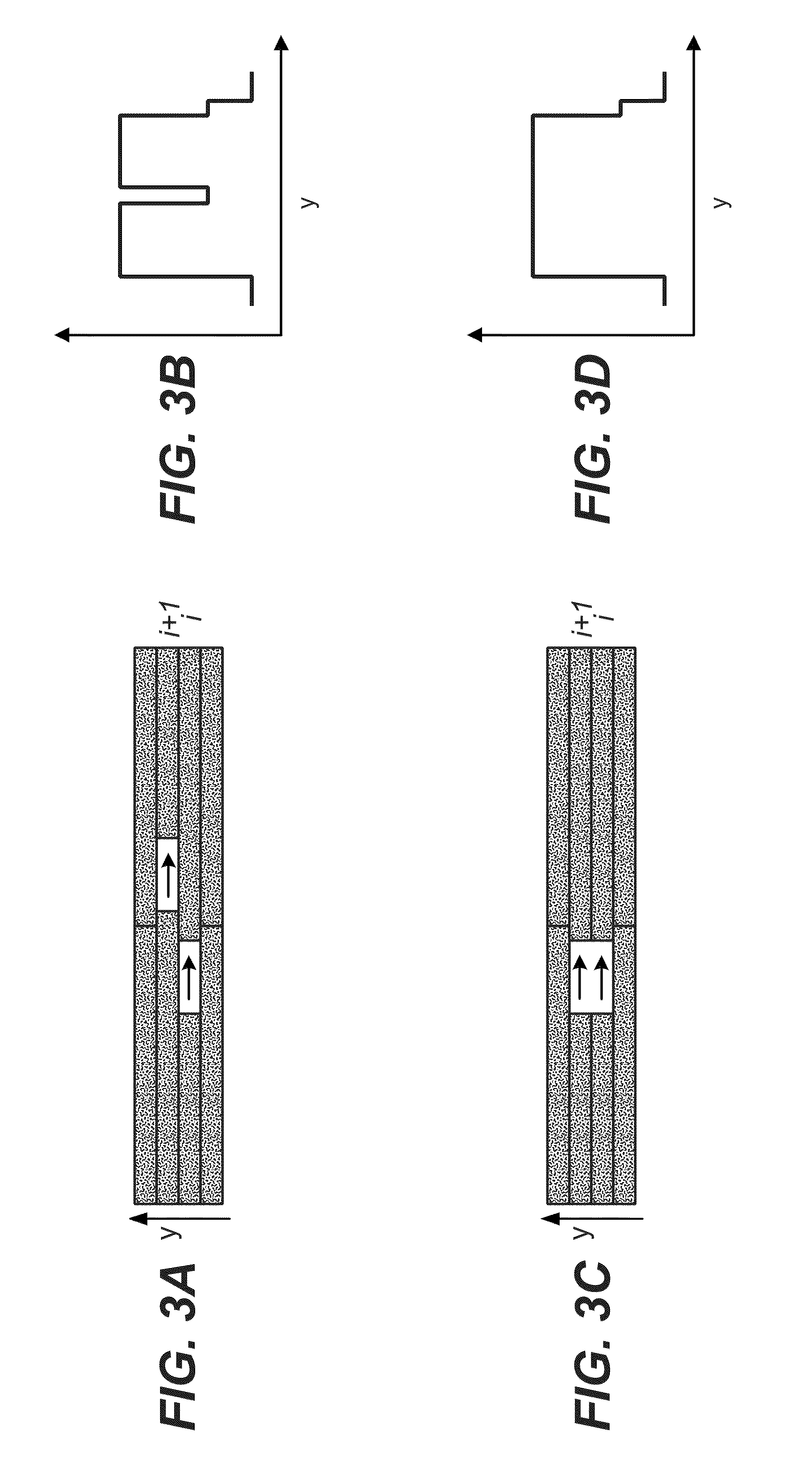
[0054]A sliding window tongue and groove optimization is presented as a simple sample of algorithm (I). No weighting is used and the MLC is coplanar, thus the leaf pairs are well defined. It is also assumed that the tongue of leaf pair i+1 is directed towards leaf pair i. The example sliding window moves from left to right.[0055]1. Set i=1.[0056]2. Find fluence crossings between fluences i and i+1. Denote the resulting intervals Ik (FIG. 6D shows intervals 1, 2 and 3), and define the starting and stopping positions: Ik=[x0,x1].[0057]a. if Fi+1(Ik)≦Fi(Ik), as shown in intervals 1 and 3 in FIG. 6D, then, in that interval, set either[0058]i. Ci+1(x)=ai(x)−ai+1(x), which aligns the A leaves for such an interval, as in interval 1 in FIG. 6D, or,[0059]ii. Ci+1(x)=bi(x)−bi+1(x), which aligns the B leaves for such an interval, as in interval 3 in FIG. 6D, or,[0060]iii. Ci+1(x)=[ai(x)−ai+1(x)]·(1−r)+[bi(x)−bi+1(x)]·r, which makes the i+1 leaves travel in between i leaves. The parameter r con...


PUM


Abstract

The present invention provides an intensity modulated radiation therapy (IMRT) method for treating a target region that minimizes the tongue and groove effect. By minimizing that effect, striping in the final delivered fluence is reduced, which improves the overall quality of the radiation delivery. In the method, compensating functions Ci(x) are added to leaf coordinates ai(x) and bi(x) for all of the leaf pairs i in a leaf sequence algorithm, where Ci(x) is chosen to match the mechanical limitations of the MLC and to minimize non-weighted or weighted sums of the tongue and groove effects, where the weighting is time-dependent, position-dependent, or time- and position-dependent, or to minimize the total treatment time, changes to the original MLC sequence, or the tongue and groove effect distribution variance in spatial or temporal coordinates.

Description

FIELD OF THE INVENTION[0001]The present invention is related to radiation therapy systems using multi-leaf collimators and is particularly related to a method for minimizing the tongue and groove effect that produces undesirable striping in the final delivered fluence for intensity modulated radiotherapy systems.BACKGROUND OF THE INVENTION[0002]Radiation therapy for cancer treatment has been in use for several decades. Modern radiation therapy systems typically generate high intensity x-rays by bombarding a suitable target with high energy electrons. X-rays are emitted from the target in a generally conical pattern and are initially confined to a generally rectangular beam by moveable, x-ray blocking “jaws” in the head of the system. Typically, the patient is positioned about 1 meter from the x-ray target and, when fully open, the jaws define a square treatment area that is about 40 cm×40 cm at the patient plane. Rarely, however, can the system jaws alone be used implement a suitabl...

Claims


Application Information

Patent Timeline
IPC IPC(8): A61N5/10G21K1/02
CPCG21K1/046A61N5/1045A61N5/1036
Inventor SILJAMAKI, SAMI PEKKAPESOLA, KATJA MARIKA
Owner VARIAN MEDICAL SYST INT AG
Why Eureka
Try Eureka