Supercharge Your Innovation With Domain-Expert AI Agents!

Imaging system and method for loading a printing plate

a printing plate and imaging system technology, applied in the field of imaging system and printing plate loading method, can solve the problems of increasing the complexity of the height adjustment mechanism, easy damage during handling, time loss and/or increased costs

Inactive Publication Date: 2009-11-03
AGFA NV
View PDF7 Cites 0 Cited by
  • Summary
  • Abstract
  • Description
  • Claims
  • Application Information

AI Technical Summary

Benefits of technology

[0011]By adjusting the position of the input section to near the top of the multiple plate stack, an imaging system is obtained wherein the loading device can easily transfer an upper printing plate from the stack towards the input section of the imaging bed. As a consequence, the imaging system is more flexible with respect to multiple plate stacks. By rendering the input section adjustable with respect to the output section, the position of the output section can be maintained, an optimal transfer of the printing plate towards the chemical processing unit is maintained.
[0012]During the loading process of subsequent printing plates, the input section can follow the top of the stack, thereby minimizing the transfer distance of the printing plate. Also, stacks having different stack heights can thus be processed.
[0013]Moreover, the system according to the invention is also more suitable with respect to various types of stacks, such as different cassette types, multiple cassettes and / or Euro-pallets. As an example, the input section can be set from near the top of a first stack to near the top of a second stack. Further, the chance that printing plates are damaged during the transfer from the stack to the input section of the imaging bed is even reduced, as the transport distance of the printing plate from the stack to the input section is minimal during transfer.
[0015]By providing the plate imaging bed with a pivot axle for pivoting the plate imaging bed, relative good control over adjustments of the input section position can be obtained. In a preferred embodiment, the pivot axle is arranged near the output section, so that the effect of the input section position on the output section position is mainly negligible, so that good transferring conditions for transferring the printing plate towards the chemical processing unit are provided.
[0016]Advantageously, the plate imaging bed forms a stiff lever arm, so that the imaging bed and also the printing plate being processed remains substantially flat, thereby facilitating good exposure conditions.

Problems solved by technology

On this substrate, a radiation sensitive coating is provided which can easily be damaged during handling.
A disadvantage of such a loading mechanism is its complexity, causing time loss and / or increased costs.
Further, the known loading mechanism is in general only suitable for handling printing plates in a specific configuration of imaging bed and stack structure.
A further disadvantage is, that this further increases the complexity of the height adjusting mechanisms.

Method used


Image

  • Imaging system and method for loading a printing plate
  • Imaging system and method for loading a printing plate
  • Imaging system and method for loading a printing plate

Examples


Embodiment Construction

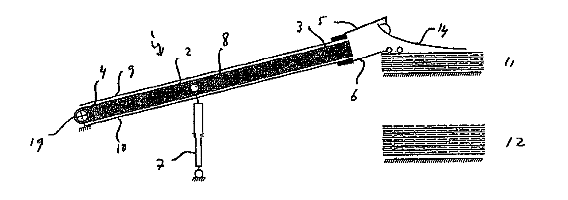
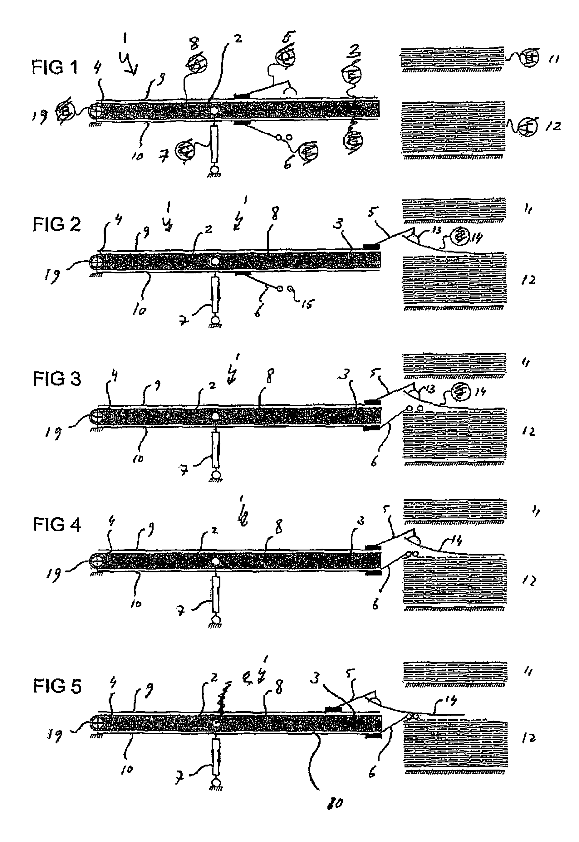
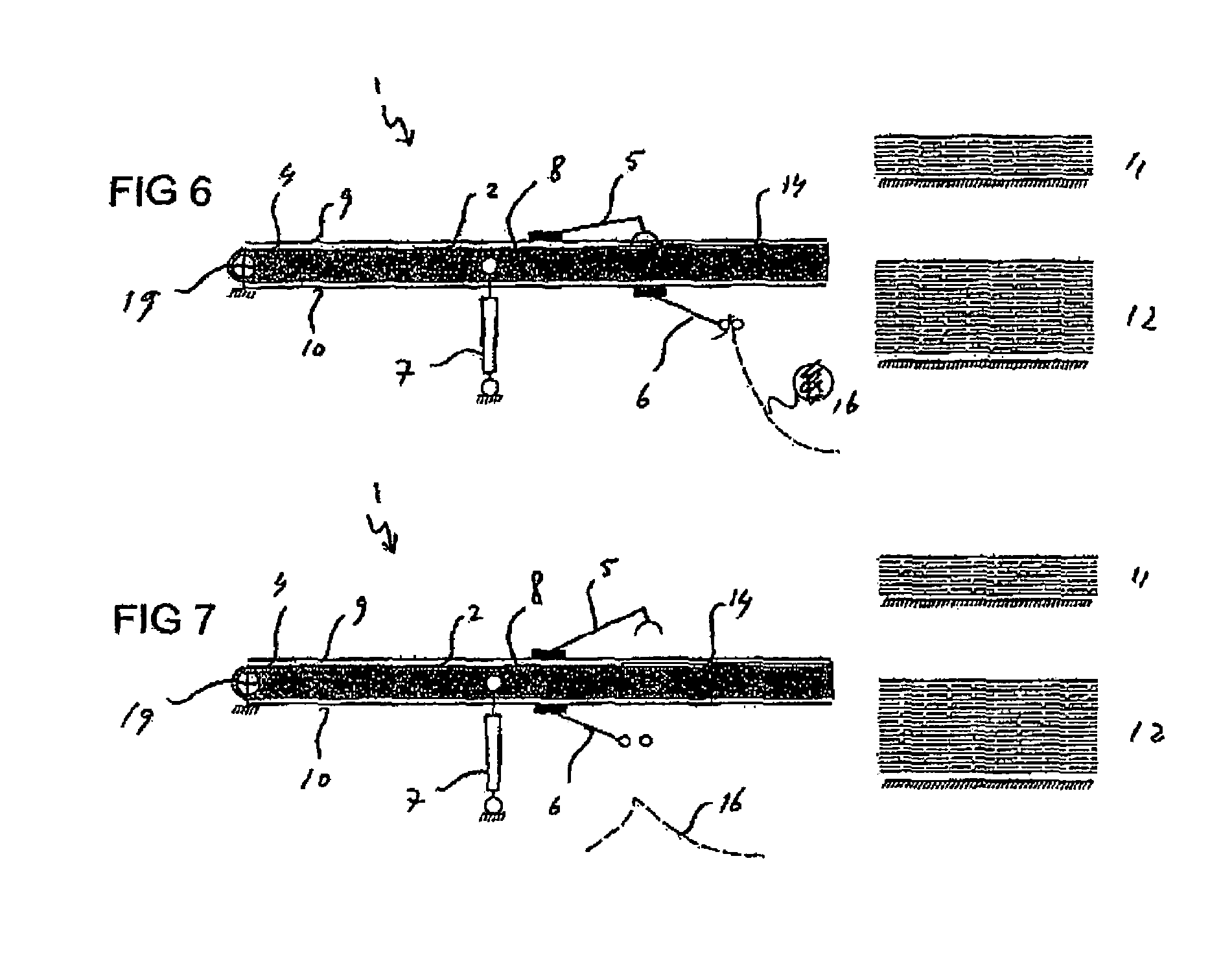
[0031]FIG. 1 shows a schematic side view of an imaging system 1 according to the invention. The imaging system 1 comprises a plate imaging bed 2 having an input section 3 and an output section 4. During a computer-to-plate imaging process, printing plates are transferred from a multiple plate stack 11, 12 to the input section 3, as will be explained in more detail below. Subsequently, the printing plate is exposed to radiation from a radiation exposure unit (not shown) that is mounted on the plate imaging process and that can comprise an imaging array or a scanning beam based exposure system such as a rotating polygon laser module. Then, the printing plate is transported to the output section 4 and transferred to a chemical processing unit (also not shown) that is placed near the output section 4.

[0032]Further, the imaging system 1 is provided with a loading device comprising a printing plate loader 5 and a paper gripper 6 for loading a printing plate from a stack to the imaging bed...


PUM

PropertyMeasurementUnit
heightaaaaaaaaaa
heightaaaaaaaaaa
time lossaaaaaaaaaa

Abstract

An imaging system for performing a computer-to-plate imaging process on printing plates includes a plate imaging bed for exposing radiation to a printing plate. The bed includes an input section for receiving a printing plate and an output section for transferring the printing plate to a chemical processing unit. The system further comprises a loading device for loading the printing plate from a multiple plate stack to the input section of the plate imaging bed. The input section is adjustable with respect to the output section to adjust the position of the input section to near the top of the multiple plate stack. The latter is accomplished in a preferred embodiment by providing the plate imaging bed with a pivot axle near the output section.

Description

CROSS-REFERENCE TO RELATED APPLICATIONS[0001]Not Applicable.STATEMENT REGARDING FEDERALLY SPONSORED RESEARCH OR DEVELOPMENT[0002]Not Applicable.BACKGROUND OF THE INVENTION[0003]The invention relates to an imaging system and a method for loading a printing plate. Traditionally, a prepress process requires the development of a negative or positive film of data to be printed. The film is subsequently copied onto a printing plate. Then, the printing plate is employed for offset printing activities. The computer-to-plate imaging process comprises a digital technology transferring text and / or images directly onto the printing plate by means of an radiation exposure unit. Thereby the intermediate film production is bypassed.[0004]A known imaging system for performing a computer-to-plate imaging process on printing plates comprises a plate imaging bed for exposing radiation to a printing plate, the bed being provided with an input section for receiving a printing plate and an output section...

Claims


Application Information

Patent Timeline
Patent Type & Authority Patents(United States)
IPC IPC(8): B41F27/12B41C3/08B41F1/28
CPCB41C1/00B65H3/40B41C1/05B41C1/10B65H2301/423245B65H2511/152B65H2511/20B65H2701/1928B65H2701/18264B65H2220/01B65H2220/02B65H2220/11B65H2511/15
Inventor WATTYN, BART MARC LUC
Owner AGFA NV
Features
  • R&D
  • Intellectual Property
  • Life Sciences
  • Materials
  • Tech Scout
  • Unparalleled Data Quality
  • Higher Quality Content
  • 60% Fewer Hallucinations
Learn More