Multilayer ceramic NOx gas sensor device

a sensor device and multi-layer ceramic technology, applied in the direction of liquid/fluent solid measurement, material electrochemical variables, instruments, etc., can solve the problems of significant interference, inability of the oxygen pump to effectively work, and easy interference from electronic noise commonly found in the automobile, so as to reduce undesired exhaust gas emissions, shorten the time to reach the temperature of operation, and speed up the sensor light off time

Inactive Publication Date: 2009-11-03
EMISENSE TECH
View PDF188 Cites 11 Cited by
  • Summary
  • Abstract
  • Description
  • Claims
  • Application Information

AI Technical Summary

Benefits of technology

[0012]The present invention is directed to a method and design for constructing the NOx sensing element of a NOx sensor system previously described in patent application Ser. No. 11 / 137,693, filed May 25, 2005, and incorporated by reference herein. The NOx sensing element comprises a multilayer ceramic structure with electrodes for sensing both oxygen and NOx gas concentrations and has included within the structure screen-printed metalized patterns that heat the ceramic sensing element to the proper temperature for optimum performance. This design provides advantages over the existing technology by miniaturizing the sensing element, which results in faster sensor light off times, thereby reducing undesired exhaust gas emissions. By incorporating the heating source within the ceramic sensing structure, the time to reach the temperature of operation is shortened and the thermal gradients and stresses are minimized, thus resulting in improved sensor performance, reliability and lifetime.

Problems solved by technology

For example, when the NOx concentration to be detected is low, residual oxygen can cause significant interference.
In addition to the above, the signal current produced by the sensor is very small, thus making it susceptible to interference from the electronic noise commonly found in an automobile.
This impairs the ability of the oxygen pump to effectively remove all of the free oxygen and may result in measurement error.
This structure has been demonstrated to be prone to clogging during use.
As a result, it is difficult to distinguish a meaningful voltage signal when both gases are present since cancellation may occur.
There are a number of limitations to this approach that have hampered the commercialization of this configuration.
In addition, the oxygen pump conversion cell tends to degrade with time, further contributing to the issue of reproducibility.
Because the effects of these concerns are magnified in the low concentration range, this measurement approach is not well suited for detecting low concentrations of NOx gases.
Additional drawbacks common to both of the sensor mechanisms discussed above stem from the fundamental design of the flat plate ceramic multilayer system.
Response times tend to be slow because of the complexity of the device requiring gas to first enter through a diffusion port, be conditioned in a first chamber, and then to diffuse into a second chamber.
Achieving rapid gas exchange that can keep up with the dynamic environment of the engine exhaust is difficult in these configurations.
Also, the corrosive nature of the gas itself and the fact that it bears fine particulates may result in the clogging of the diffusion controlling port, or at the very least, changes in the gas flow dynamics with time.
Finally, pulsations in gas flow rates due to cylinder firings and the electrical noise typical of automobiles make it difficult to control and monitor the low voltage and current circuits associated with these devices.

Method used


Image

  • Multilayer ceramic NOx gas sensor device
  • Multilayer ceramic NOx gas sensor device
  • Multilayer ceramic NOx gas sensor device

Examples


example 1

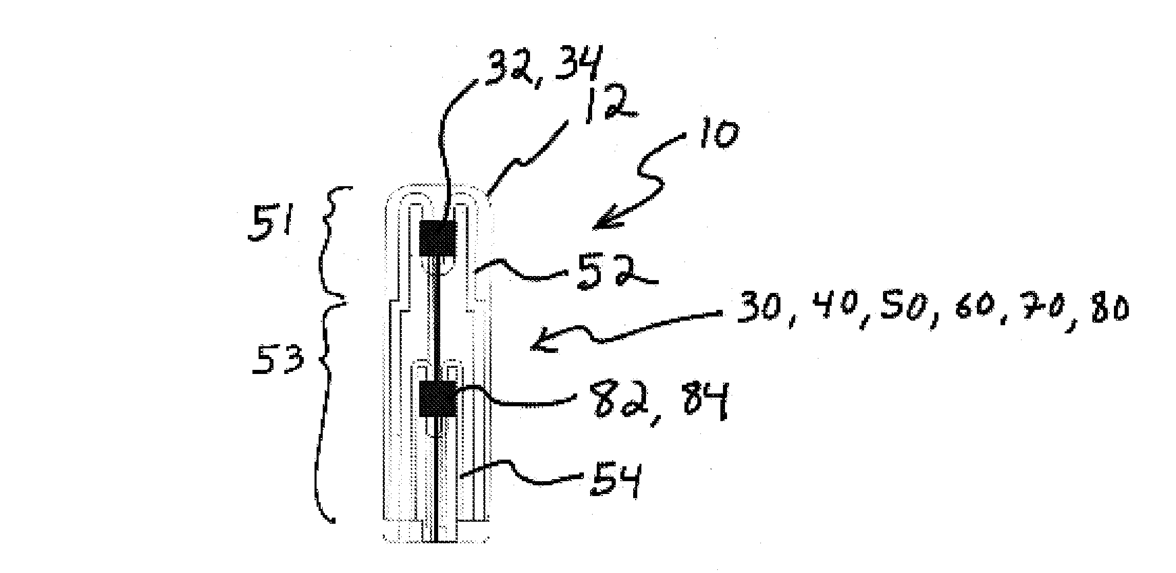
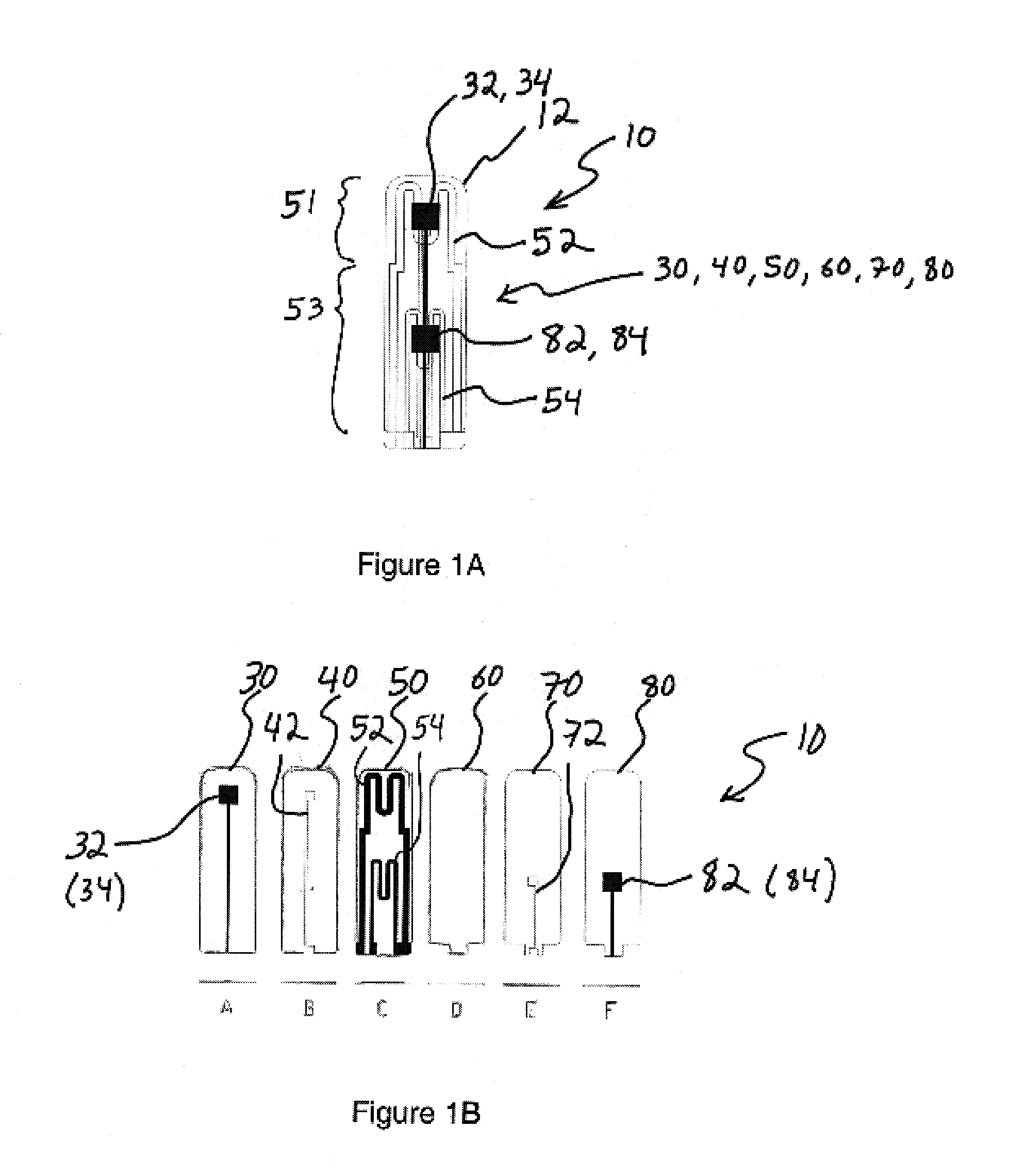
[0031]Referring first to FIG. 1A, the basic features of the multilayer gas sensor element 10 are illustrated. More specifically, the gas sensor element 10 is shown in a schematic view such that features of the individual layers 30, 40, 50, 60, 70, 80 used to make up the sensor body 12 are shown to overlap as they would in the completed sensor element 10. This view illustrates the relationship between features of the sensor element 10.

[0032]In the sensor element 10, the oxygen sensor 32 is positioned spacially near the heater element 52, but on an outer face of the element 10. A reference electrode 34 is positioned on an inner face of the oxygen sensor layer 30 in a substantially similar position. As a result, when viewed as in FIG. 1A, the oxygen sensor 32 and reference electrode 34 overlap. Similarly, the NOx sensor 82 is positioned spacially near the heater element 54 on an outer surface of the element 10. A reference electrode 84 is positioned on an inner face of the NOx sensor l...

example 2

[0042]While there are many advantages to the planar multilayer sensor element 10 characterized in Example 1 above, it may also be advantageous to utilize similar processing techniques to produce a multilayer sensor element 110 in the form of a tubular sensor body 112, as illustrated in FIG. 5. FIG. 5 shows a conceptual schematic of a multilayer tubular sensor element 110 which, like the sensor element 10 of FIGS. 1A-4B, incorporates two different heating zones 151, 153, along with both an oxygen sensing electrode 132 and a NOx sensing electrode 182. Both sensors 132, 182 share a common air reference electrode 134. It should be noted that the first and second heating zones 151, 153 illustrated in FIG. 5 are not in practice discrete zones, but are temperature regions with no concrete border separated instead by a continuum of intermediate temperatures.

[0043]To fabricate the tubular sensor element 110 illustrated in FIG. 5, the first step was to produce a ceramic tubular multilayer str...


PUM

PropertyMeasurementUnit
temperatureaaaaaaaaaa

Abstract

A mixed potential NOx sensor apparatus for measuring the total NOx concentration in a gas stream is disclosed. The NOx sensing apparatus comprises a multilayer ceramic structure with electrodes for sensing both oxygen and NOx gas concentrations and includes screen-printed metalized patterns that function to heat the ceramic sensing element to the proper temperature for optimum performance. This design may provide advantages over the existing technology by miniaturizing the sensing element to provide potentially faster sensor light off times and thereby reduce undesired exhaust gas emissions. By incorporating the heating source within the ceramic sensing structure, the time to reach the temperature of operation is shortened, and thermal gradients and stresses are minimized. These improvements may provide increased sensor performance, reliability, and lifetime.

Description

GOVERNMENT RIGHTS[0001]This invention was made in part with government support under Grant Numbers 68-D-02-076 and 68-D-03-061 awarded by the United States Environmental Protection Agency. The Government has certain rights in the invention.RELATED APPLICATIONS[0002]This application is related to and claims the benefit of U.S. patent application Ser. No. 11 / 137,693, of Balakrishnan Nair, Jesse Nachlas, and Michael Middlemas filed on May 25, 2005, and entitled “NOx Sensor Method and Device” and U.S. Provisional Patent No. 60 / 574,622 of Balakrishnan Nair, Jesse Nachlas, and Michael Middlemas filed on May 26, 2004, and entitled “NOx Gas Sensor Method and Device.” Each of these applications is incorporated herein by reference in their entirety.FIELD OF THE INVENTION[0003]The present invention relates in general to the measurement of NOx gases in exhaust streams generated from the combustion of hydrocarbons, and more particularly, to the measurement of NOx gases in exhaust gas streams pro...

Claims


Application Information

Patent Timeline
Patent Type & Authority Patents(United States)
IPC IPC(8): G01N27/407
CPCG01N27/4067G01N27/26
Inventor NAIR, BALAKRISHNAN G.NACHLAS, JESSE
Owner EMISENSE TECH
Why Eureka
Try Eureka