
Manufacturing method that uses laser surface transformation to produce new and unique surface profiles for rotating bearings

a technology of rotating bearings and surface profiles, which is applied in the direction of photomechanical equipment, manufacturing tools, instruments, etc., can solve the problems of large open pores in the surface, high tribological stress on the connecting rods and main bearing shells of the crankshaft journal, and high wear and deterioration of the crankshaft,

Active Publication Date: 2009-11-03
ADCOLE CORP +1
View PDF4 Cites 0 Cited by
  • Summary
  • Abstract
  • Description
  • Claims
  • Application Information

AI Technical Summary

Benefits of technology

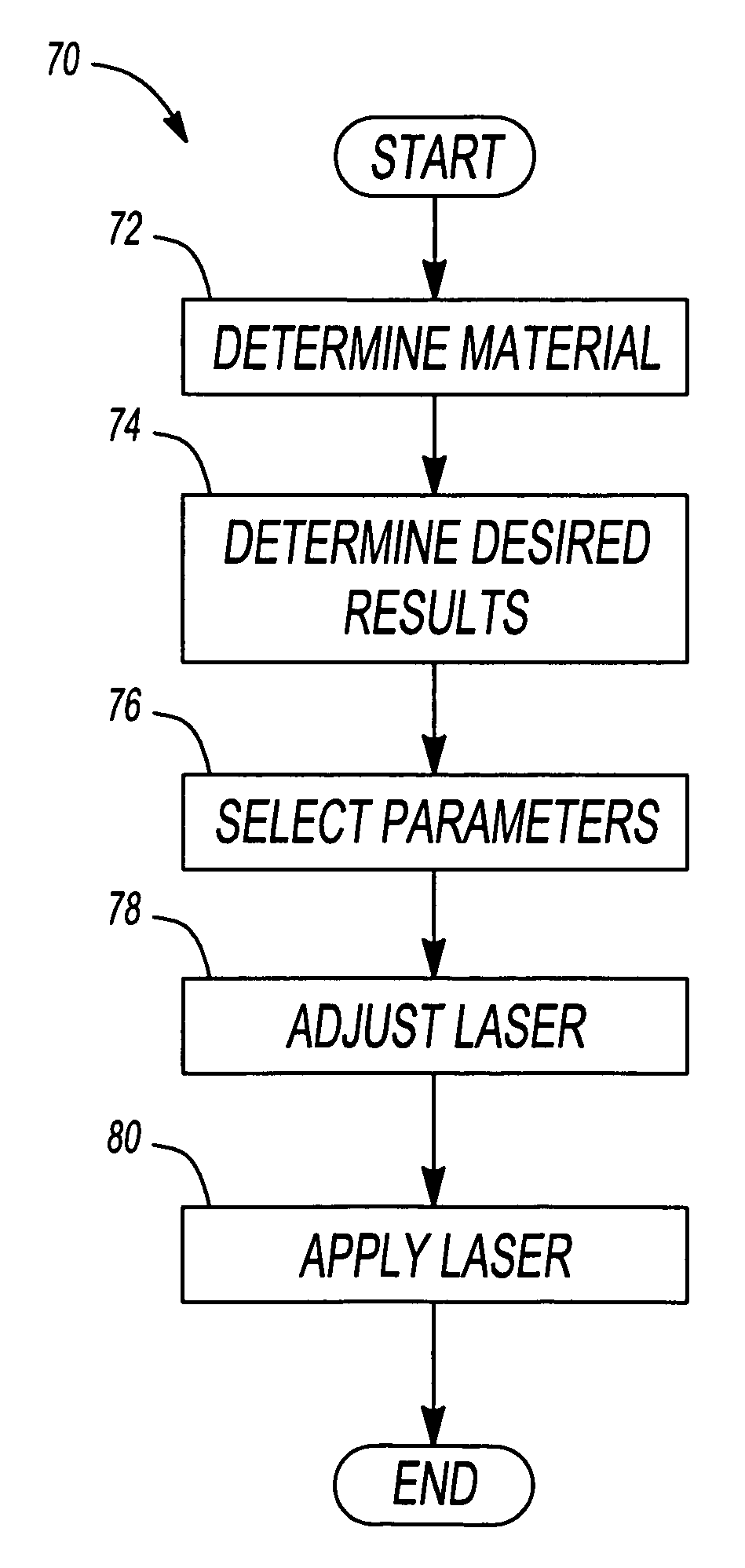
The patent describes a method for using a laser to change the surface of an automotive component. This involves determining the desired characteristics of the surface and selecting parameters for the laser ablation device. The laser is then generated and applied to the surface, creating oil-retention reservoirs. The technical effect of this method is the ability to create precise and consistent surface modifications on automotive components, improving their performance and durability.

Problems solved by technology

Connecting rods and main bearing shells of the crankshaft journal are subject to high tribological stress.
Therefore, crankshafts, crankshaft bearings, and connecting rod bearings are highly susceptible to wear and deterioration due to heat, pressure, abrasion, and loss of lubrication.
The abrasive material, such as abrasive tape or stone, removes the inclusions, but often leaves a relatively large open pore in the surface.
These projecting edges are commonly called “ferrite caps” or “hooks.” After assembly in an engine, these ferrite caps may break off, forming small abrasive particles that lead to premature bearing failure.

Method used


Image

  • Manufacturing method that uses laser surface transformation to produce new and unique surface profiles for rotating bearings
  • Manufacturing method that uses laser surface transformation to produce new and unique surface profiles for rotating bearings
  • Manufacturing method that uses laser surface transformation to produce new and unique surface profiles for rotating bearings

Examples


Embodiment Construction

[0014]The following description of the preferred embodiment is merely exemplary in nature and is in no way intended to limit the invention, its application, or uses.

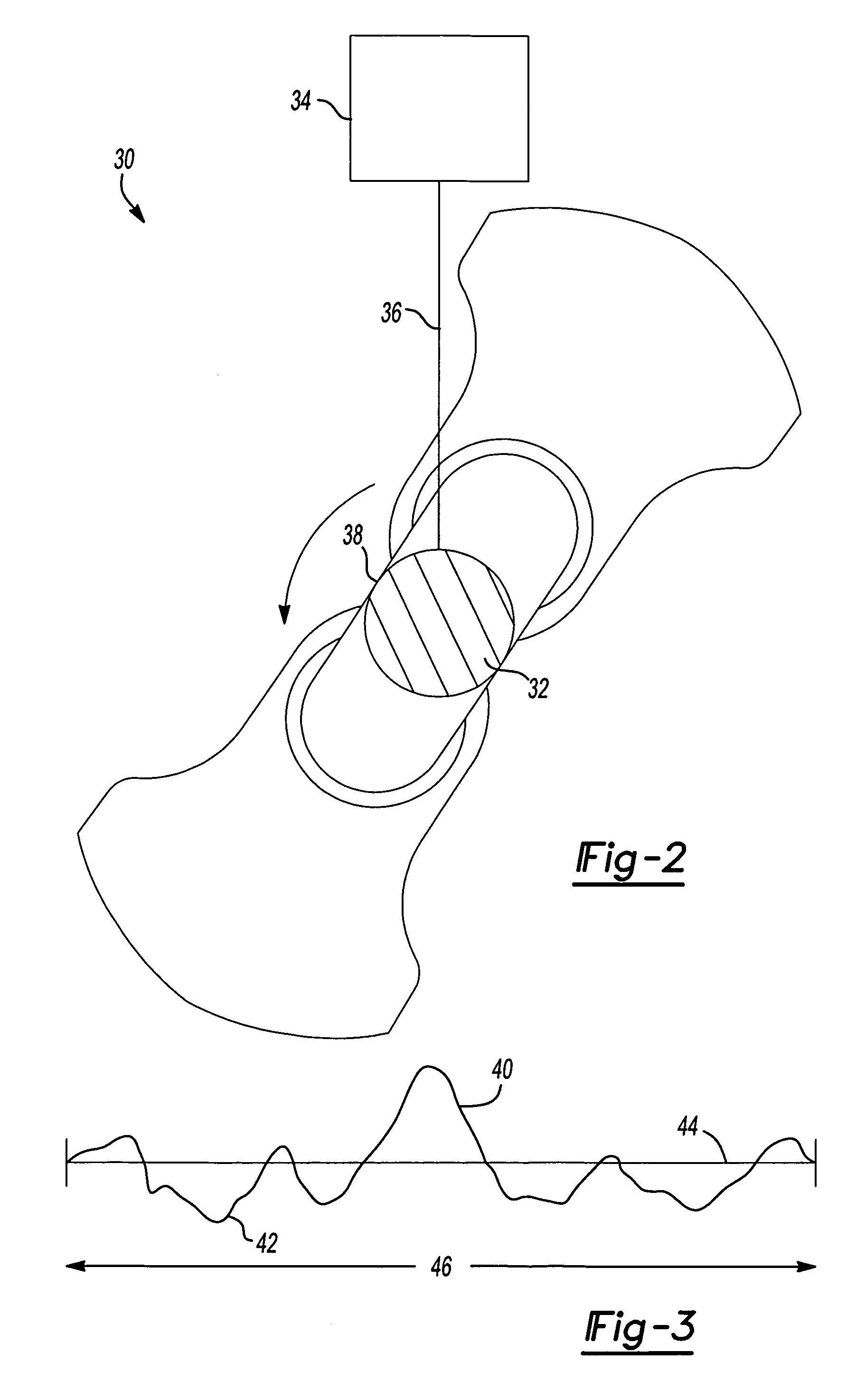
[0015]The laser ablation process of the present invention completely changes the waviness and form of surface roughness by increasing the slope of the various peaks, which translates into increased bearing surface. Hence the material roughness may measure the same, or somewhat rougher, after laser ablation, but the tribology is substantially improved due to flatter slopes. A laser ablation system 30 includes a crankshaft 32 (shown in cross-section) and a laser ablation device 34 as shown in FIG. 2. The laser ablation device 34 generates and applies a laser 36 to a crankshaft bearing surface 38. As a result, the crankshaft bearing surface 38 achieves a higher roughness and a lower friction relative to a surface treated by conventional abrasion techniques.

[0016]The surface profile of automotive crankshafts, as well as vari...


PUM

PropertyMeasurementUnit
wavelengthaaaaaaaaaa
heat absorptionaaaaaaaaaa

Abstract

A laser ablation method is used to polish a bearing surface of an automotive crankshaft. A laser ablation device generates a laser according to parameters such as wavelength, pulse duration, pulse repetition rate, and beam quality. The laser is applied to the surface of a rotating engine component, such as a crankshaft, as the component is rotated in order to polish the surface according to the parameters. The laser substantially improves tribological performance of the bearing surface by changing the waviness and form of the surface profile. Further, oil-retention reservoirs are formed in the surface. As a result, the friction coefficient of the crankshaft surface is reduced while the roughness of the crankshaft surface is maintained, reduced, or increased.

Description

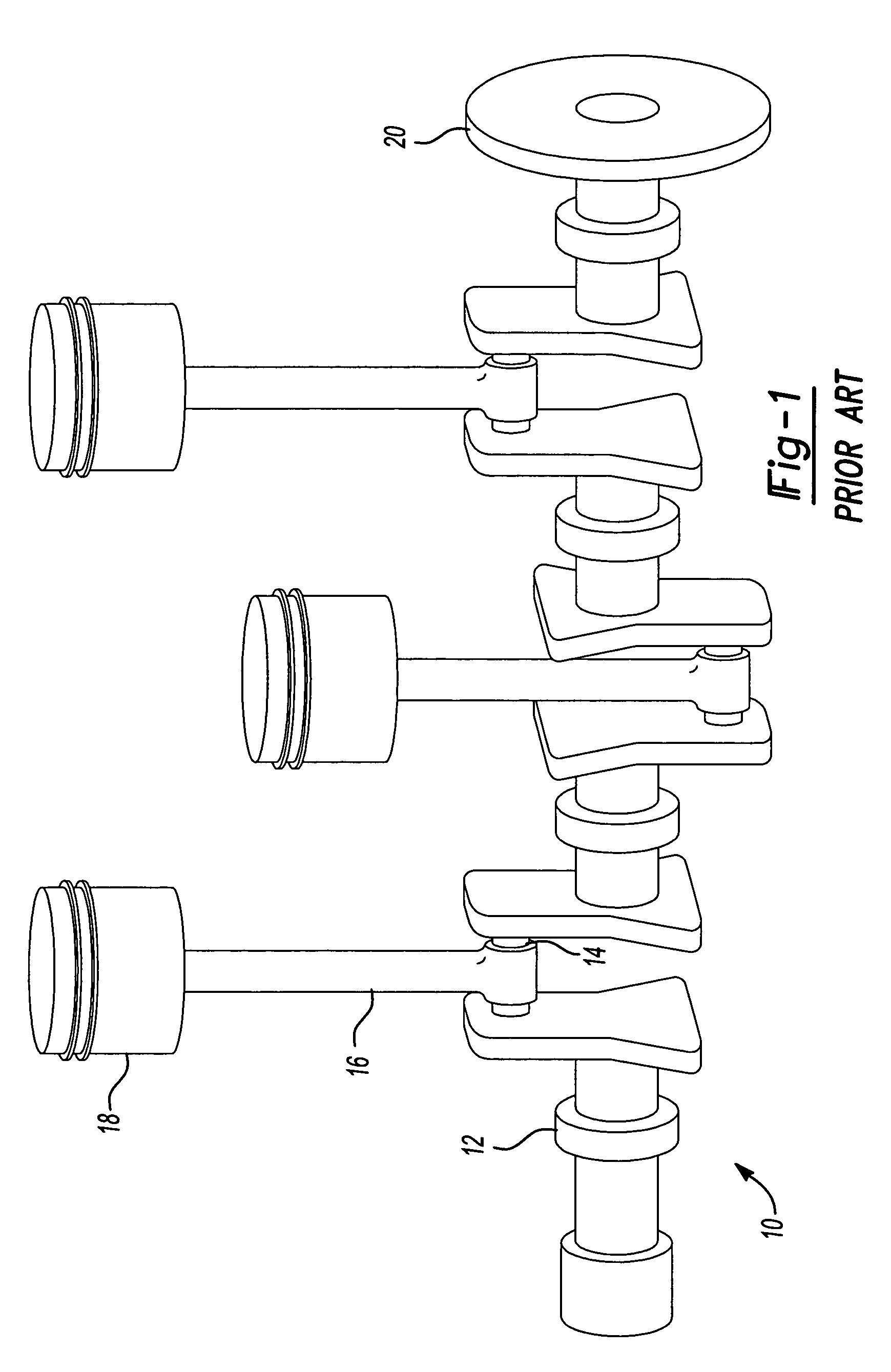
CROSS-REFERENCE TO RELATED APPLICATIONS[0001]This application claims the benefit of Provisional Patent Application Ser. No. 60 / 638,941, filed Dec. 23, 2004.FIELD OF THE INVENTION[0002]The present invention relates to modifying the surface finish of automotive rotation component bearing surfaces, and more particularly to modifying surface waviness and form using laser ablation.BACKGROUND OF THE INVENTION[0003]The surface profile of a material is a combination of roughness, waviness, and form. To produce bearing surfaces that meet performance requirements, conventional surface finishing reduces the roughness by polishing the ground bearing surfaces, such as pins and main bearing journals on an automotive crankshaft. An automotive crankshaft 10 is shown in FIG. 1. The automotive crankshaft 10 includes crankshaft bearings 12 and connecting rod bearings 14. Connecting rods 16 connect the crankshaft 10 to pistons 18. As the pistons 18 translate within the engine cylinders (not shown), the...

Claims


Application Information

Patent Timeline
Patent Type & Authority Patents(United States)
IPC IPC(8): B23K26/00G03F7/26
CPCB23K26/0075B23K26/0078B23K26/367B23K26/063B23K26/06B23K26/0622B23K26/364B23K26/3576B23K26/3584
Inventor BUSTAMANTE, ANTHONY TWILT, JOHN
Owner ADCOLE CORP
Learn More