Switchgear with movable user interface module

a user interface module and switchgear technology, applied in the field of switchgear installations, can solve the problems of operator exposure to potentially operator exposure to high levels of arc flash energy, and operator exposure to the potential of arc flash incident, and achieve the effect of convenient removal

Inactive Publication Date: 2009-11-03
RESA POWER LLC
View PDF27 Cites 11 Cited by
  • Summary
  • Abstract
  • Description
  • Claims
  • Application Information

AI Technical Summary

Benefits of technology

[0014]All new AC low voltage air circuit breakers and insulated case circuit breakers are provided with overload protection by the circuit breaker mounted solid state tripping systems. Older low voltage air circuit breaker and insulated case circuit breakers can have their electromechanical overloads removed and replaced. Retrofitting these breakers with the new solid state tripping system of the present invention will result in a much safer working environment since the operator will no longer have to enter the cubicle since a user interface module will be able to be remote from the circuit breaker mounted logic module and the new module may be secured in position on each cubicle door or may be totally remote. It should be noted that all existing, new low voltage circuit breakers can also benefit from having their existing solid state tripping systems retrofitted with the modules proposed in this application.
[0016]It is an object of the present invention to provide a novel switchgear installation in which the operator can perform the set up, querying, and monitoring functions while safely outside of the cubicle.
[0018]Another object is to provide such an installation in which a single user interface module may be used to perform the necessary operator functions for a multiplicity of circuit breakers, thus reducing the cost of installing and maintaining the installation.
[0019]A further object is to provide such an installation wherein redundant modules are avoided and thereby less costly.SUMMARY OF THE INVENTION

Problems solved by technology

In prior instances, operating personnel assigned to make adjustments, to set parameters, perform queries and monitor information, deal with battery functions available on solid state trip devices of low voltage circuit breakers, were exposed to potentially high levels of arc flash energy during the process.
More particularly, the operator has been exposed to high levels of arc flash energy because the module or modules controlling setup, monitoring, battery and querying functions were mounted on the circuit breaker itself and it was behind the protective front door of the circuit breaker cubicle.
When mounted in the electrical system, these electro-mechanical tripping devices could only be accessed by opening the front door of the circuit breaker cubicle, thus exposing the operator to the potential of an arc-flash incident.
This system was large, expensive and cumbersome.
The initial devices were complex, circuit breaker mounted, and provided no monitoring capabilities.
This is, as stated, redundant and is costly.
With this process, the operator still has the option to setup, monitor, query or deal with battery function on the inside of the circuit breaker cubicle, thus exposing himself to a potential arc flash hazard.
Once again, the operator is exposed to arc flash hazards while dealing with the setup, monitoring, battery and querying functions
Large controllers which, because of their size, are unable to be mounted on all low voltage circuit breaker cubicle doors have been provided in external cabinets.
While these devices may provide levels of setup, query or monitoring functions for low voltage circuit breakers, they have always been redundant to the complete solid state trip devices that were mounted on the circuit breakers.
These controllers represent a great expense beyond and above the cost of a solid state tripping device and still allow the operator to be exposed to the potential of an arc flash hazard if entry to the cubicle is required.
In prior cases, the battery was mounted in a module which was mounted inside the front door of the circuit breaker cubicle, thus potentially exposing an operator who wanted to deal with the battery functions, to the potential of arc flash energy.
Not only is the operator in the now hazardous approach zone, but also the operator is faced with having to perform the required functions with less dexterity because of the gloves, and with impaired vision because of the tinted face shield.

Method used


Image

  • Switchgear with movable user interface module
  • Switchgear with movable user interface module
  • Switchgear with movable user interface module

Examples


Embodiment Construction

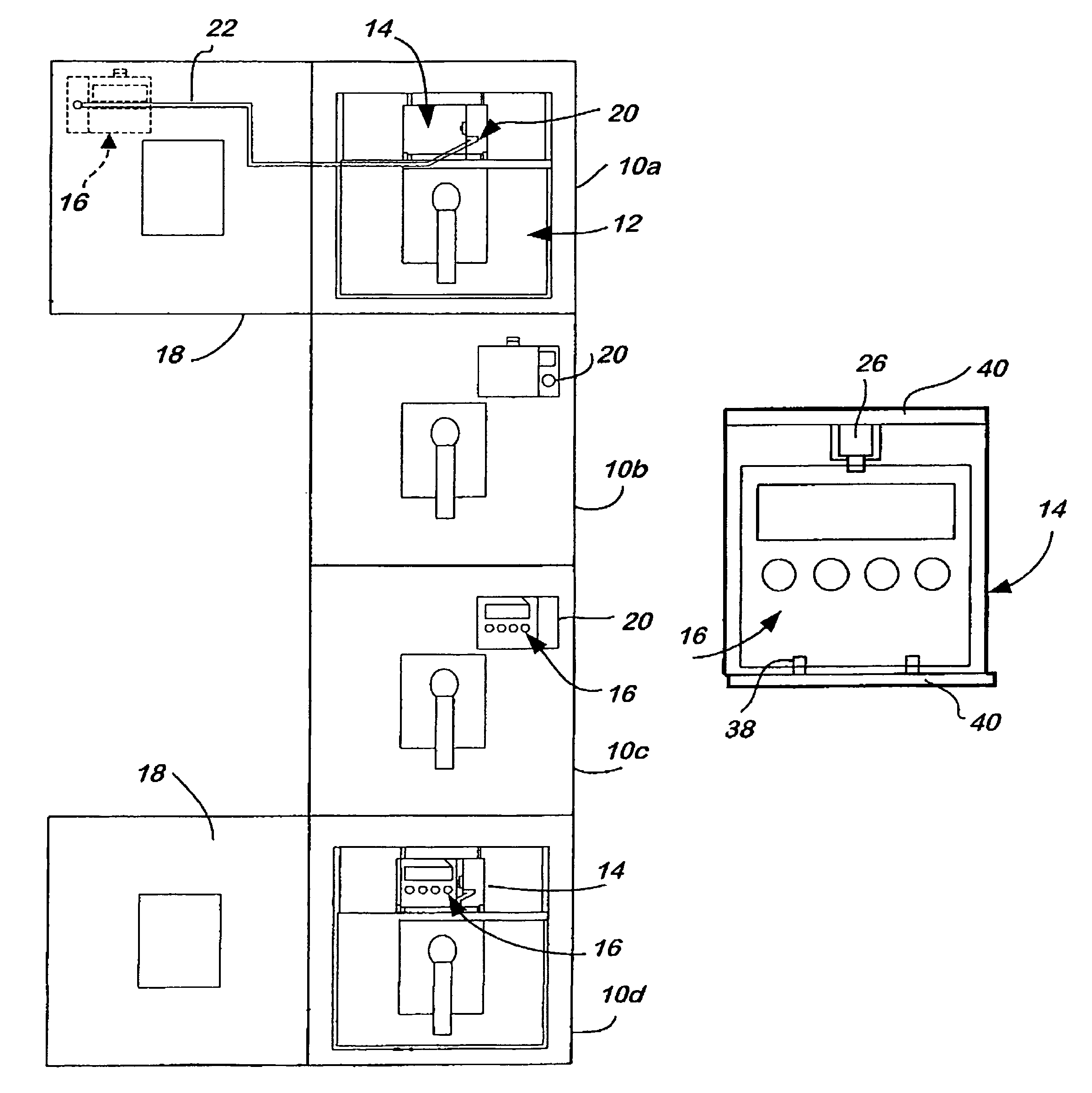
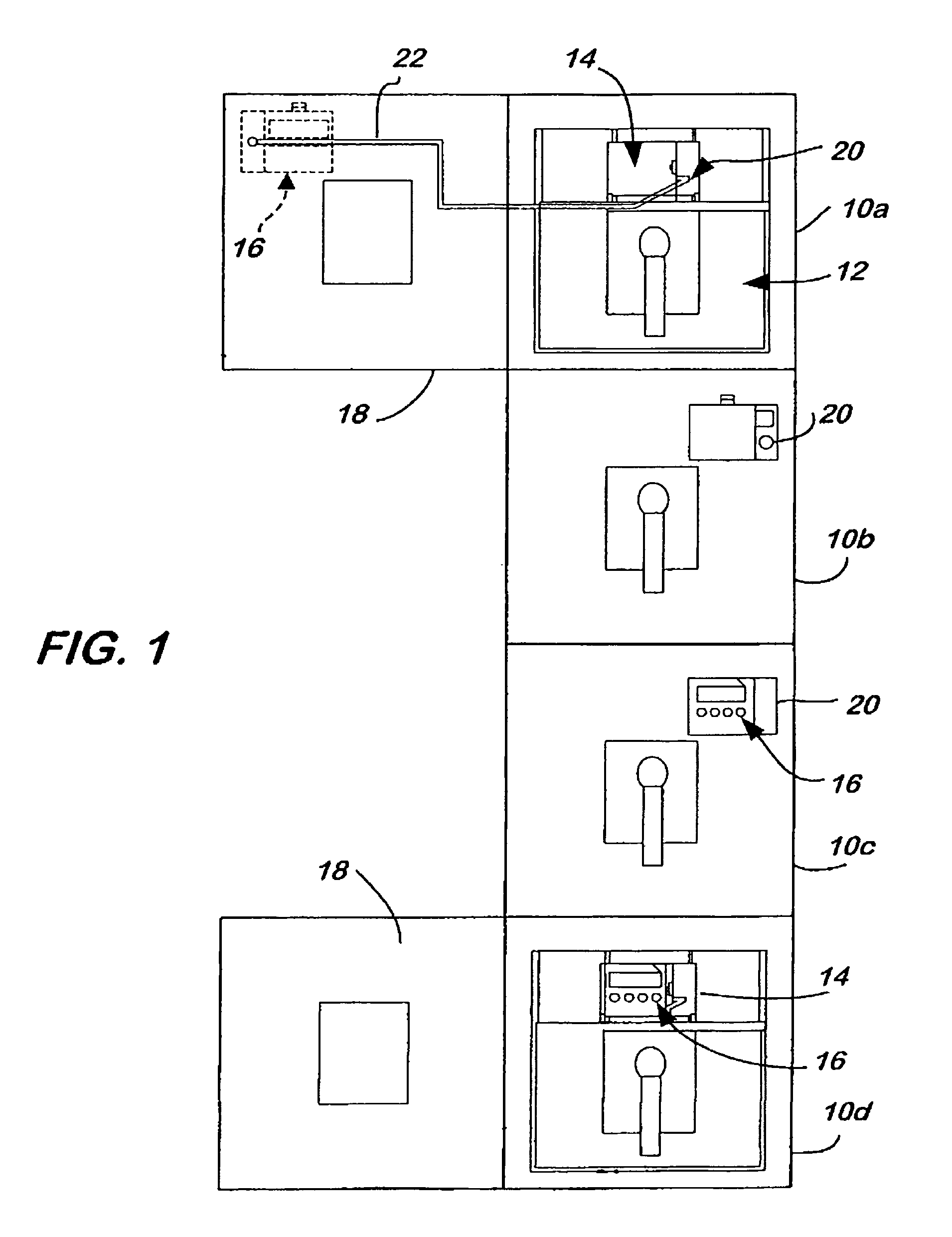
[0040]As discussed previously, the present invention separates the circuitry and components required for monitoring and controlling the operation of the circuit breaker into two modules with the logic module being mounted upon the breaker and the mounting, querying and setting up functions being provided in a movable user interface module which can be utilized while outside the cubicle housing the breaker. The user interface module contains a battery to provide the power needed for operation of both modules. Only one user interface module is required for a switchgear installation since the user interface module can be removed quickly and easily from the mounting bracket or docking station on the door of one cubicle to the docking stations of other cubicles.

[0041]The attached drawings illustrate a preferred construction, but modifications may be made to deal with unique configurations and requirements.

[0042]Turning first to FIG. 1, therein illustrated is a switchgear installation inc...


PUM


Abstract

A switchgear installation has a cubicle with a door to provide access thereinto, and a low voltage circuit breaker is mounted therein and accessible through the door. Coupled to the circuit breaker is a logic module, and a portable user interface module is releasably mounted on the exterior of the cubicle and operatively connected to the logic module to display information concerning the operation of the breaker and to provide an interface for the user to interact with the logic module and thereby with the breaker. The user interface module includes a battery providing the required power for setting and monitoring the functions of the breaker.

Description

[0001]The present invention relates to switchgear installations utilizing low voltage power circuit breakers.[0002]Low voltage circuit breaker and insulated case circuit breakers 635_vac and below, are utilized to open and close electrical circuits in every power plant and nearly every factory in the world. In prior instances, operating personnel assigned to make adjustments, to set parameters, perform queries and monitor information, deal with battery functions available on solid state trip devices of low voltage circuit breakers, were exposed to potentially high levels of arc flash energy during the process.[0003]More particularly, the operator has been exposed to high levels of arc flash energy because the module or modules controlling setup, monitoring, battery and querying functions were mounted on the circuit breaker itself and it was behind the protective front door of the circuit breaker cubicle.[0004]Prior to the invention of solid state tripping systems, low voltage air ci...

Claims


Application Information

Patent Timeline
Patent Type & Authority Patents(United States)
IPC IPC(8): H02B1/26G01F1/00H02B1/36
CPCH01H71/123H01H71/74H01H2071/006
Inventor ULINSKAS, ALGERD M.
Owner RESA POWER LLC
Why Eureka
Try Eureka