Solar energy storage system

Active Publication Date: 2009-11-10
FOI GRP
View PDF32 Cites 35 Cited by
  • Summary
  • Abstract
  • Description
  • Claims
  • Application Information

AI Technical Summary

Benefits of technology

[0008]In this invention, the storage containers are rotated in and out of a solar energy collection point by a conveyor system and can then be transported to different storage areas to heat secondary storage containers or to be used in processes such as cooking, powering heat engines, water heating, absorption refrigeration, or adsorption cooling. The energy collection point is located at a focal point of solar energy reflected and collected by a three-level reflector system

Problems solved by technology

Conventional systems of photovoltaics and solar heating are hampered by high cost, low efficiency, unpredictable power output, and the need for backup power or heat sources.
However, collection and storage for later use ha

Method used


Image

  • Solar energy storage system
  • Solar energy storage system
  • Solar energy storage system

Examples


Embodiment Construction

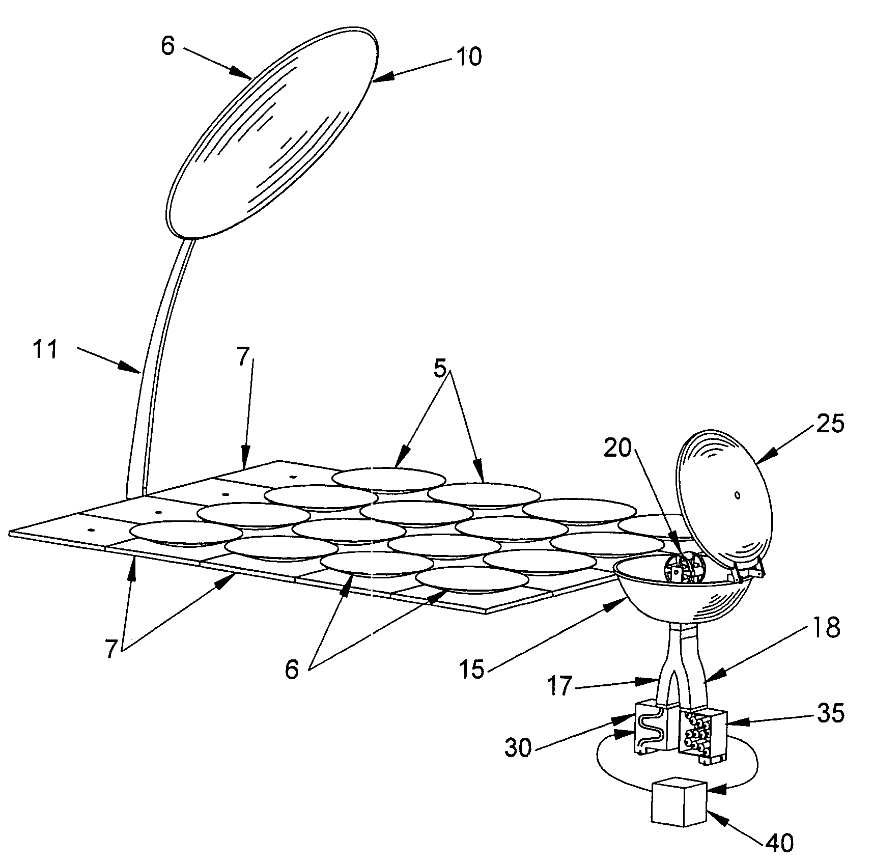
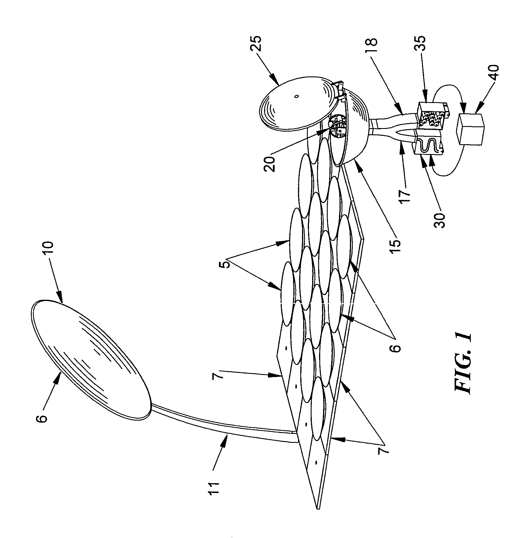
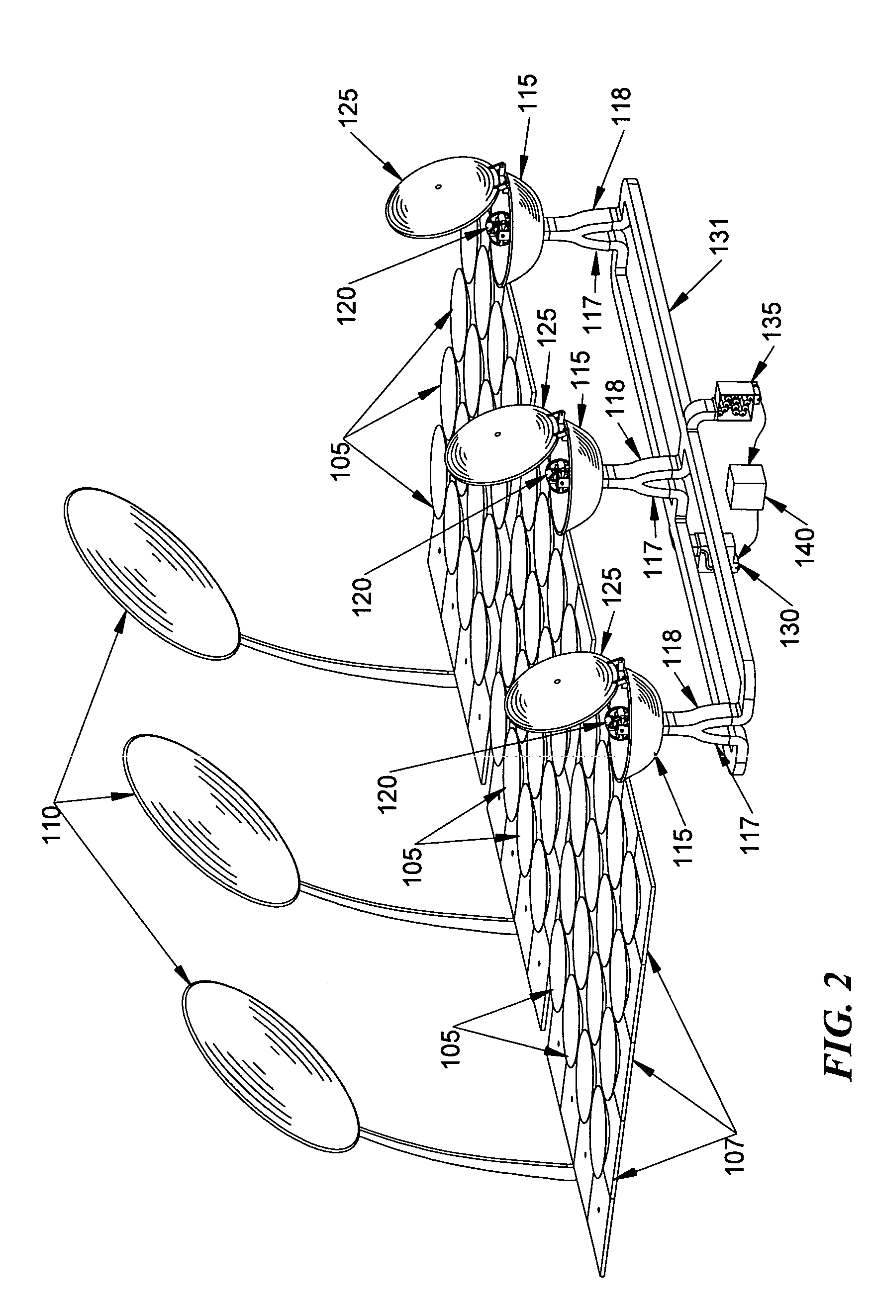
[0019]This invention is an energy absorption and distribution system in which mobile heat storage containers can be transported to areas in need of a clean and reliable source of energy. The invention uses a three-level arrangement of mirror reflectors to concentrate solar energy onto the mobile heat storage containers and conserve heat during this process.

[0020]FIG. 1 shows a basic arrangement for the invention that can be used on any flat surface. This flat surface can also be a building roof, vehicle roof (e.g. parked truck trailer, rail car, aircraft, etc), or other constructs.

[0021]An array of primary mirrors 5 are arranged on a mounting surface 7. Although a flat surface is envisioned, other embodiments may be designed that are used on irregular surfaces. This primary mirror array 5 collects and concentrates solar energy onto a secondary mirror 10. At least one of these mirrors (e.g. on each mirror in the entire mirror array 5 or the secondary mirror 10) are preferably equippe...


PUM


Abstract

A method and apparatus for storing, transporting, and releasing high grade, thermodynamically useful energy for a wide variety of uses. Solar energy is collected and reflected onto a heat storage container using a three-mirror reflecting system. This invention involves a method of heating the heat storage container using a primary, secondary, and tertiary system, which has a core that is partially comprised of an aluminum alloy and a metallic shell with a higher melting point than the aluminum alloy contained within. Once heated, the storage containers can then be transported to different storage areas in order to heat secondary storage containers or can be used in processes such as cooking, powering heat engines, water heating, absorption refrigeration, or drying garbage, waste, or biomass.

Description

RELATED APPLICATION DATA[0001]This application is related to Provisional Patent Application Ser. No. 60 / 599,983 filed on Aug. 9, 2004, and priority is claimed for this earlier filings under 35 U.S.C. §120. The Provisional Patent Application is also incorporated by reference into this utility patent application.TECHNICAL FIELD OF THE INVENTION[0002]An apparatus and method for capturing solar energy within a heat storage container in order to effectively and efficiently utilize the resulting heat energy by transporting, storing, and putting the energy to productive use.BACKGROUND OF THE INVENTION[0003]Conventional systems of photovoltaics and solar heating are hampered by high cost, low efficiency, unpredictable power output, and the need for backup power or heat sources. Much of the energy consumption in the modern age revolves around climate control, refrigeration, and the cooking of food. Solar energy potentially offers an important source of heat energy. However, collection and st...

Claims


Application Information

Patent Timeline
IPC IPC(8): F24J2/34
CPCF24J2/12F24J2/18F24J2/34F24J2/4609F24J2/5417Y02E10/47F24J2002/108F24J2002/109Y02E10/42F24S23/71F24S23/79F24S30/45F24S40/10F24S60/00F24S2023/872F24S2023/876Y02E10/40
Inventor MUNSON, JR., DAVID MURRAY
Owner FOI GRP
Why Eureka
Try Eureka