
Method, system and program storage device for simulating fluid flow in a physical system using a dynamic composition based extensible object-oriented architecture

a technology of dynamic composition and storage device, applied in the field of method, system and program storage device for simulating fluid flow in a physical system using a dynamic composition, can solve the problems of unfavorable scientific programming application, so as to minimize the effect of combinatorial expansion

Active Publication Date: 2009-11-10
SCHLUMBERGER TECH CORP +1
View PDF24 Cites 44 Cited by
  • Summary
  • Abstract
  • Description
  • Claims
  • Application Information

AI Technical Summary

Benefits of technology

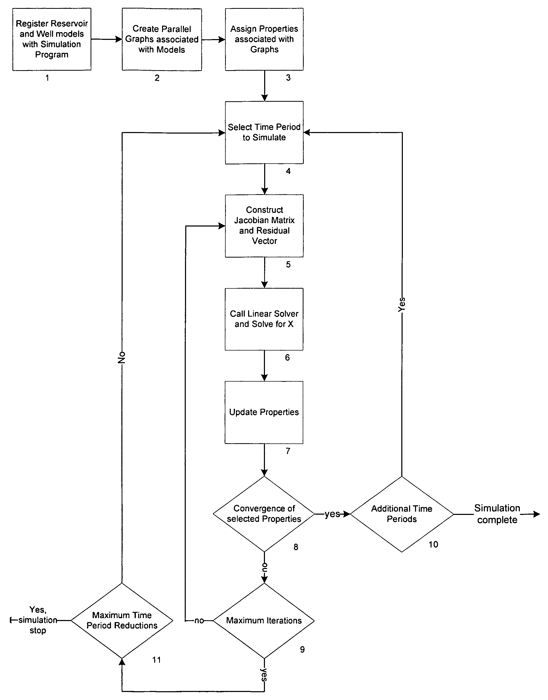
The present invention provides a method for simulating the flow of fluid in a physical system using a composition-based program. The program includes a framework subsystem, an engine subsystem, and a set of model components. The engine subsystem creates a model object representative of the physical system, which is then run to simulate fluid flow in the physical system. The method also includes criteria to define common characteristics of properties values and a partition package for creating partition objects containing subset objects of node and edge indices. The composition-based class hierarchy between the engine subsystem, framework subsystem, and model components minimizes the combinatorial expansion when adding new compute classes. The reservoir simulator has dynamic partitioning of node indices based upon changing properties of the reservoir model over timesteps.

Problems solved by technology

Although object-oriented design has been the main staple of software development for quite some time, its application to scientific programming has been hindered somewhat by the perceived inefficiency of run-time polymorphism.
As new software development technologies are invented it is often the case that architectures that adopt these technologies first suffer for a variety of reasons.
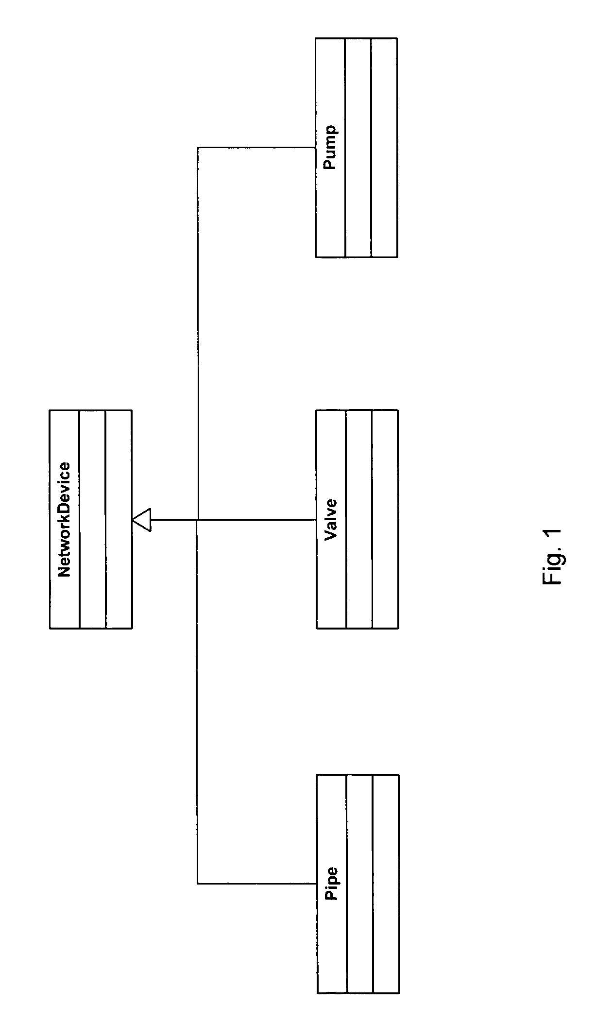
The misuse of inheritance, a technique commonly associated with code reuse and extendibility, often leads to unnecessary complexity and a low rate of code reuse with increasing program requirements.
While the “is-a” relationship provides a simple rule for classification and results in rapid development of class hierarchies, as functional requirements of the program expand reliance heavily on inheritance can result in complex hierarchies that are difficult to reuse or extend.
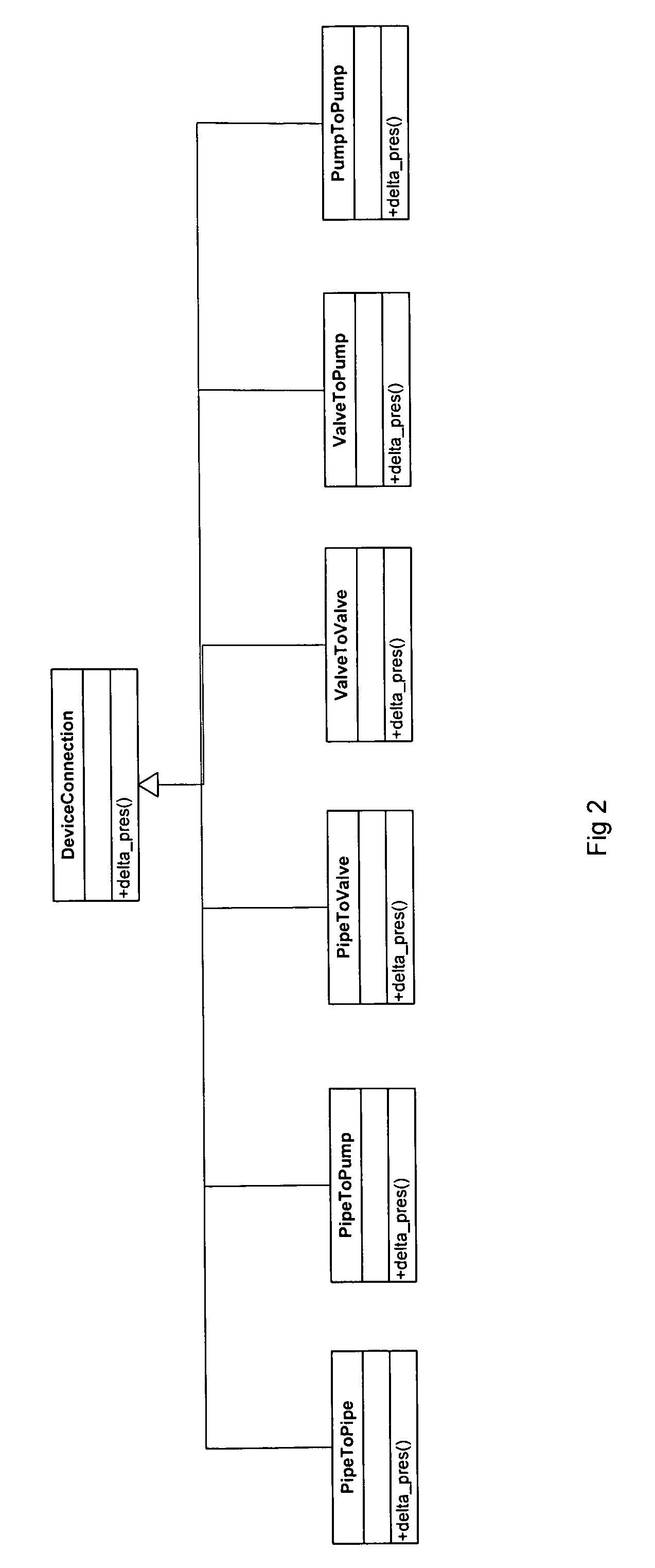
As a result of the combining of these concepts of physical type and compute type in derived classes, a disadvantageous complexity is created.
The addition of new device and compute types will result in a combinatorial growth in the number of DeviceConnection derived classes and lead to an overly complex architecture.
This could be avoided by placing limits on the number of device and compute types but the architecture cannot then be considered extendable.
Furthermore, while the same class structure is used to add new devices and compute types, the DeviceConnection architecture is not extendable without modification.
The decision to include system behavior methods such as pressure and temperature change (i.e., delta_pres( ) and delta_temp( ) methods) directly in the hierarchy defining device connectivity (i.e., the class PipeToPipe defines a connection between two pipe devices) results in modifications to the DeviceConnection base class with the addition of new behaviors and leads to potentially monolithic base classes.
Due to the research nature of the codes, provisions for computational options such as adaptive implicit, required of commercial simulators, were not included in the class hierarchy and thus limited the number of specialized connection classes.

Method used


Image

  • Method, system and program storage device for simulating fluid flow in a physical system using a dynamic composition based extensible object-oriented architecture
  • Method, system and program storage device for simulating fluid flow in a physical system using a dynamic composition based extensible object-oriented architecture
  • Method, system and program storage device for simulating fluid flow in a physical system using a dynamic composition based extensible object-oriented architecture

Examples


Embodiment Construction

A. Introduction

[0043]The present invention provides solutions to the shortcomings cited in the background section by using the object-oriented technique of composition as the basis of class hierarchies, coupled with a different decomposition of the class architecture. Inheritance is an extremely tight coupling mechanism while composition is simply embedding a class within another class and therefore provides much greater control over the degree of coupling. The embedded class is called the implementation class while the composed class is called the interface class. This technique is often referred to as the handle / body or bridge pattern. The approach promotes clear specification of the roles and responsibilities of the interface class, insulates clients of the architecture from changes in the implementations and results in a simpler architecture. A composition-based hierarchy can easily support dynamic configuration of program behavior to optimize the configuration of computation cl...


PUM


Abstract

The present invention provides a method, a system and a program storage device containing instructions for simulating the flow of fluid in a physical system using a composition-based extensible object-oriented program. A computer program includes: (i) a framework subsystem providing a graph package, a compute package and a property package; (ii) an engine subsystem including engine subsystem packages for performing numerical simulation, the engine subsystem packages including a linear solver package and a non-linear solver package; and (iii) a set of model components providing physical and numerical modeling behaviors utilized by the engine subsystem, the model components including at least one of a reservoir model, a well model, an aquifer model, a fluid model and a SCAL model. The framework subsystem, the engine subsystem and the model components work with one other to simulate the flow of fluid. Preferably, a partition package is used to create a partition of subsets of node and edge indices which can be used optimize computations by the program.

Description

[0001]This application claims benefit of U.S. Provisional Application No. 60 / 631,661, filed Nov. 29, 2004, which is incorporated by reference herein in its entirety.BACKGROUND OF THE INVENTION[0002]Hydrocarbon exploration and recovery rely on sophisticated means of reservoir modeling. Reservoir models can be used to understand geology and fluid flow, or predict future production using a variety of recovery mechanisms. General-purpose reservoir simulators are used to integrate geologic, petrophysical, fluid and well model descriptions with physical laws governing mass transport to support reservoir analysis and prediction. A good primer on the principles behind reservoir simulation is Aziz, K. and Settari, A., Petroleum Reservoir Simulation. Elsevier Applied Science Publishers, London (1979). Reprinted by Khalid Aziz and Antonin Settari, Blitzprint Ltd., Calgary, Alberta (2002).[0003]Simulation of reservoir models requires solution of equations which govern conservation of mass and e...

Claims


Application Information

Patent Timeline
Patent Type & Authority Patents(United States)
IPC IPC(8): G06G7/50
CPCG06F17/5009G06F17/5018G06F2217/16G06F2111/10G06F30/23G06F30/20G06F30/28G06F2113/08
Inventor CHILDS, PAULDEBAUN, DAVID R.BYER, THOMAS J.
Owner SCHLUMBERGER TECH CORP
Learn More