Flow control redistribution to mitigate high cycle fatigue

a flow control and high cycle fatigue technology, applied in the direction of machines/engines, combustion-air/fuel-air treatment, transportation and packaging, etc., can solve the problems of reducing engine performance, poor performance, and uneven above-effects of the engine, so as to reduce the weight and cost of the engin

Active Publication Date: 2009-11-17
LOCKHEED MARTIN CORP
View PDF6 Cites 48 Cited by
  • Summary
  • Abstract
  • Description
  • Claims
  • Application Information

AI Technical Summary

Benefits of technology

[0010]The present invention provides a system and method to improve pressure recovery and distortion of an engine inlet that substantially addresses the above-identified needs. This method involves providing a first fluid flow to primary jet vortex generators operable to inject fluid at a first injection rate into a boundary layer of a primary fluid flow within the inlet. A secondary fluid flow is injected by secondary jet vortex generators at a second injection rate into the boundary layer of the primary fluid flow. Fluid injected at the first injection rate and second injection rate are operable to induce secondary flow structures within the boundary layer. These secondary close structures are operable to improve pressure recovery and distortion of the inlet. At specific engine conditions, this method redistributes the ratio of the first injection rate and second injection rate in order to change the distortion pattern of the inlet when particular engine conditions exist. Such particular engine conditions may include a natural blade frequency of the engine at a particular speed. This allows blade vibration problems associated with the engine with engine operation at particular speeds to be addressed without adding damping or increasing blade strength to change the natural frequency of the blades. This avoids additional weight and improves engine performance.
[0011]Another embodiment in the present invention provides an inlet control system that may change the distortion pattern within a flow inlet. This inlet flow control system includes a first manifold, primary jet vortex generator(s), a second manifold, secondary jet vortex generator(s), and a control system. The first manifold and second manifold supply fluid flow to the primary jet vortex generator(s) and secondary jet vortex generator(s), respectively. The jet vortex generator(s) may be located on duct surfaces within the flow inlet. The jet vortex generators inject fluid received from the pressure manifolds at adjustable injection rate(s) into the boundary layer of the ducted primary fluid flow within the flow inlet. The primary and secondary jet vortex generators induce secondary flow structures within the boundary layer that manipulate the flow within the flow inlet in order to change the distortion pattern of the inlet. As many variables may affect the distortion pattern of the flow inlet, an active control system may redistribute the ratio of the fluid injected by the primary vortex generator(s) and the secondary vortex generator(s) in order to achieve an improved distortion pattern of the flow inlet.
[0012]Additional embodiments may include sensors that sense engine conditions such as a specific speed corresponding to a blade frequency. In other embodiments, sensors may sense the circumferential distortion across a compressor face of an engine coupled to the flow inlet. By comparing engine conditions or circumferential distortion to predetermined or desired values, the fluid injected by the vortex jet generators may be redistributed when the circumferential distortion across the compressor face compares unfavorably to a desired circumferential distortion or when the engine is operating at a particular harmonic or speed associated with a blade number. In either case, this allows the weight and cost associated with the engine to be reduced as blades may not require extra hardening in order to operate the engine at the predetermined blade frequencies.

Problems solved by technology

The above effects are not uniform over the face of the engine.
Flow field vortices generated by fluid flow over aerodynamic surfaces within the inlet can cause buffet and fatigue any downstream structure exposed to these vortices and reduce engine performance.
Additionally, these vortices can be ingested within engine air intakes or other like air inlets leading to poor performance, excessive blade vibration, and / or stalling of the aircraft engines.
Stalling the aircraft engine and / or excessive blade vibration create a potentially hazardous conditions.
Additionally, exotic aperture shapes for the inlet and outlet may cause excessive propulsion performance losses.
Compressor face distortion can lead to high amplitude circumferential harmonics at critical engine speeds causing excessive vibration of fan or compressor blades, leading to blade failure due to high cycle fatigue.
Any of these changes may involve increased cost and weight associated with the aircraft.
However, these vanes result in increased weight and reduced performance over the entire operating envelope of a vehicle.
Since a variety of factors effect pressure recovery and distortion of the inlet, the airflow may not best served by a passive flow control.
As the aircraft may maneuver and engine air flow requirements may change, a single solution is not best suited to improve the pressure recovery and distortion of the engine inlet over the operating envelope of the aircraft.

Method used


Image

  • Flow control redistribution to mitigate high cycle fatigue
  • Flow control redistribution to mitigate high cycle fatigue
  • Flow control redistribution to mitigate high cycle fatigue

Examples


Embodiment Construction

[0022]Preferred embodiments of the present invention are illustrated in the figures like numerals being used to refer to like and corresponding parts of the various drawings.

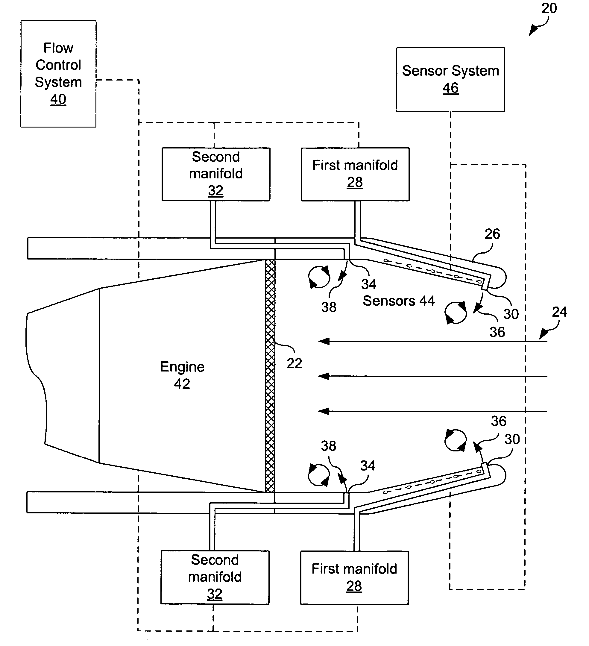
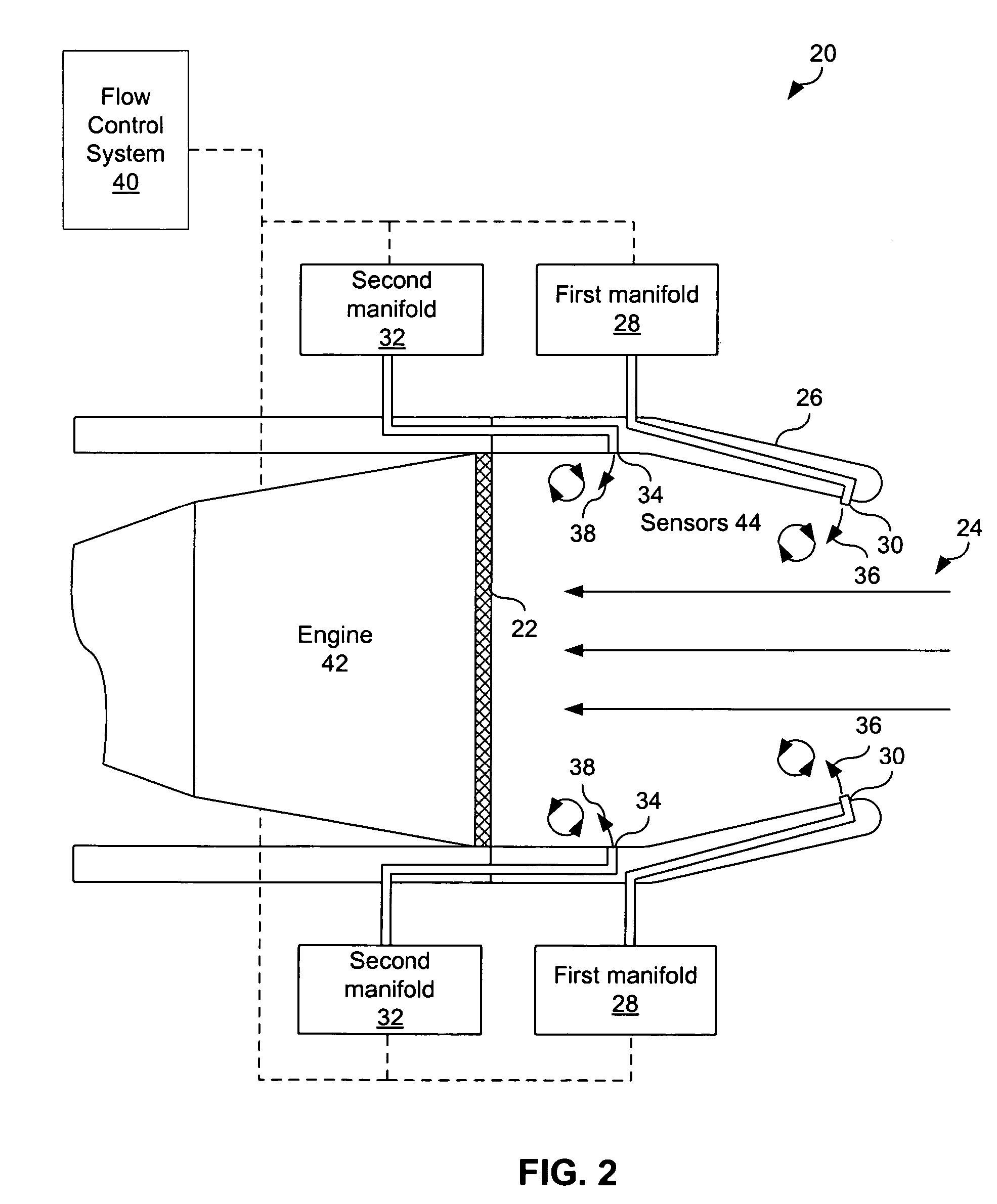
[0023]The present invention provides a system and method for manipulating fluid flow within an inlet that substantially eliminates or reduces disadvantages and problems associated with previously developed systems and methods. More specifically, the present invention provides a system and method to improve pressure recovery and distortion within a flow inlet and reduce buffeting or fatigue to engine components through the use of jet vortex generators. This system and method includes the placement of jet vortex generators on surfaces bounding the fluid flow. These jet vortex generators manipulate the flow behavior at this boundary of the fluid flow, to reduce flow separation within the primary fluid flow and improve pressure recovery and distortion.

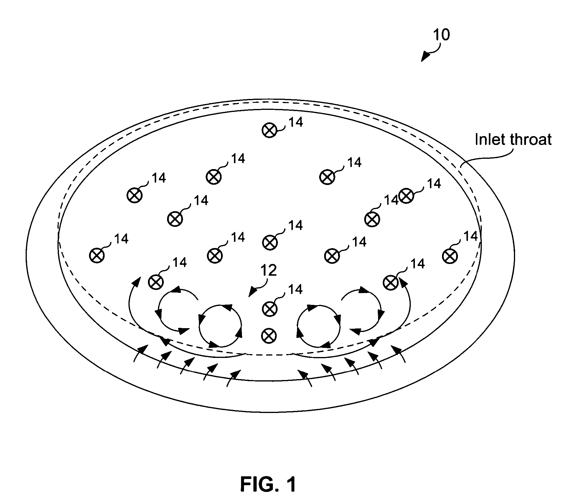
[0024]FIG. 1 provides a three dimensional flow field within a duc...


PUM


Abstract

A method operable to improve pressure recovery and / or distortion within engine inlet is disclosed. A first fluid flow is provided to primary jet vortex generator(s) operable to inject fluid at a first injection rate into a boundary layer of a primary fluid flow within the inlet. A secondary fluid flow is injected by secondary jet vortex generator(s) at a second injection rate into the boundary layer of the primary fluid flow, The fluid injected at the first injection rate and second injection rate is operable to induce secondary flow structures within the boundary layer. These secondary close structures are then operable to improve or manipulate the pressure recovery of the inlet. At specific engine conditions, this method may redistribute the ratio of the first injection rate and second injection rate in order to improve pressure recovery and / or distortion of the inlet when the particular engine conditions.

Description

CROSS REFERENCE TO RELATED PATENTS[0001]This application incorporates by reference and claims priority under 35 USC § 119(e) to a provisionally filed patent application entitled “FLOW CONTROL REDISTRIBUTION TO MITIGATE HIGH CYCLE FATIGUE,” and having a filing date of Mar. 31, 2006, and an application No. 60 / 744,109.TECHNICAL FIELD OF THE INVENTION[0002]The present invention relates generally to manipulation of fluid flow and more particularly, a system and method for manipulating fluid flow within an engine inlet duct to mitigate the level of vibration of engine compression system components.BACKGROUND OF THE INVENTION[0003]Most modern aircraft are powered by gas turbine engines, also known as jet engines. There are several types of jet engines, but all jet engine propulsion systems have certain parts in common. For example, all jet engine propulsion systems have an inlet with which to bring in free stream air into the engine. The inlet sits upstream of the compressor and, while the...

Claims


Application Information

Patent Timeline
Patent Type & Authority Patents(United States)
IPC IPC(8): F02K3/00
CPCF02C7/04F05D2270/18Y10S415/914Y10T137/0536Y10T137/0645
Inventor TRUAX, PHILIP P.MILLER, DANIEL N.MA, EDWARD C.
Owner LOCKHEED MARTIN CORP
Why Eureka
Try Eureka