Variable characteristic venous access catheter shaft

a catheter shaft and variable technology, applied in the field of medical devices, can solve the problems of increasing the difficulty of insertion, reducing the long-term durability of the catheter shaft, and uncomfortable catheters for patients

Inactive Publication Date: 2009-11-17
ANGIODYNAMICS INC
View PDF17 Cites 42 Cited by
  • Summary
  • Abstract
  • Description
  • Claims
  • Application Information

AI Technical Summary

Benefits of technology

[0018]According to the principles of the present invention, a central venous catheter having a proximal tube segment, a distal tube segment and a transition tube segment interposed between the proximal and distal tube segments is provided. The three segments are preferably formed as a single integrated tube containing polymer material of different durometer and different amounts of radiopaque filler material. The polymer durometer of the proximal segment is higher than the

Problems solved by technology

While these catheters are biocompatible and designed to minimize indwelling side effects and optimize patient comfort, they do have several drawbacks.
The soft material characteristics of the catheter provide patient comfort but increase insertion difficulties and reduce the long-term durability of the catheter.
While this design provides a soft, atraumatic distal end allowing a stiffer, more rigid shaft body, the catheter is uncomfortable to the patient because the majority of the shaft is stiff.
In addition, the physician cannot customize the length of these catheters by cutting at the tip, as is commonly done in the practice.
Most venous access catheters do not have sufficient radiopacity to allow for easy visualization of the distal tip.
The drawback of this enhanced tip design is that it prevents the physician from cutting the tip to customize the length of the PICC line.
The design also requires a bond or weld joint, which decreases the overall strength of the catheter and increases the risk of fracture at the bond or weld point.
Although providing an acceptable level of visibility, the highly filled shaft material had poor fatigue and chemical resistance, which resulted in an increased occurr

Method used


Image

  • Variable characteristic venous access catheter shaft
  • Variable characteristic venous access catheter shaft
  • Variable characteristic venous access catheter shaft

Examples


Embodiment Construction

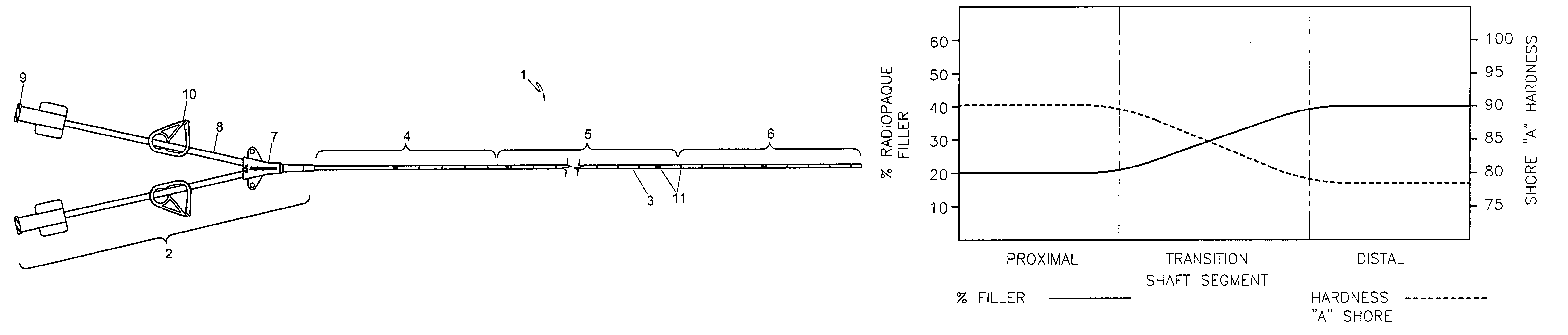
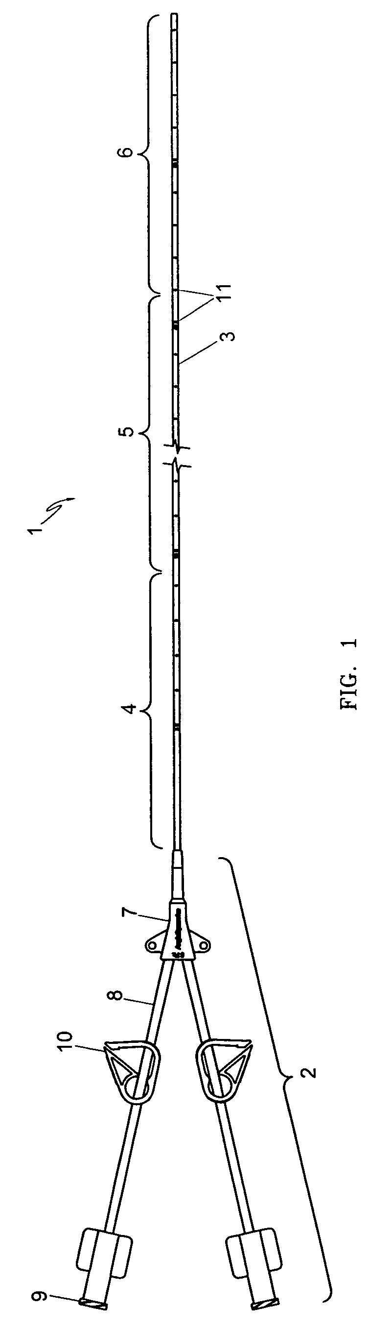
[0028]Referring to FIG. 1, a variable characteristic PICC line of the present invention is shown from a plan view. The catheter 1 is comprised of a hub section 2, a tube or shaft 3 with a substantially rigid proximal segment 4, a transition segment 5 and a substantially flexible distal segment 6. In the embodiment shown, a dual-lumen catheter is provided. In this embodiment, the hub 2 is further comprised of a bifurcated hub component 7 and two extension legs 8 corresponding to each shaft lumen, as is well known in the art. The extension legs 8 terminate at the proximal end with a connector such as a standard luer fitting 9 for connection to injection or aspiration devices. Leg clamps 10 coaxially arranged around the extension legs 8 may be used to clamp off or occlude the leg lumens, preventing the inflow or outflow of fluids through the catheter 1. The catheter may include measurement markers 11 to assist in placement within the vessel.

[0029]According to the present invention, a u...


PUM


Abstract

A central venous catheter is provided having a proximal tube segment, a distal tube segment and a transition tube segment interposed between the proximal and distal tube segments which are preferably formed as a single integrated tube containing polymer material of different durometer and varying amounts of radiopaque filler material. The polymer durometer of the proximal segment is higher than the polymer durometer of the distal segment. By contrast, the percentage by weight of the filler material contained in the distal segment is higher than that of the proximal segment. The variation in the polymer durometer and the filler amount along the length of the tube provide the desired tensile strength, hardness, chemical resistance and fatigue resistance at the proximal segment and at the same time provide the desired flexibility and radiopacity at the distal segment.

Description

CROSS-REFERENCE TO RELATED APPLICATIONS[0001]This application claims priority to U.S. provisional application No. 60 / 430,998, filed Dec. 4, 2002, which is incorporated herein by reference.FIELD OF THE INVENTION[0002]The present invention relates to a medical device apparatus and method for the delivery and withdrawal of fluids and medications. More particularly, the present invention relates to a venous access catheter device with variable shaft characteristics and method of manufacture.BACKGROUND OF THE INVENTION[0003]Venous access catheters provide venous access to the central circulatory system. Venous access catheters include central venous catheters, dialysis catheters and peripherally inserted central catheters, also known as PICC lines. The access line is used for the delivery of intravenous fluids, medications such as chemotherapy drugs and antibiotics, and blood products. Venous access catheters may also be used as access mechanisms for blood sampling and the administration...

Claims


Application Information

Patent Timeline
IPC IPC(8): A61M25/00A61MA61M1/00A61M1/36A61M25/01A61M25/098A61M25/16
CPCA61L29/18A61M1/3659A61M25/0108A61M25/0054
Inventor APPLING, WILLIAM M.
Owner ANGIODYNAMICS INC
Why Eureka
Try Eureka