De-rotation system for a counter-rotating, coaxial rotor hub shaft fairing

a technology of rotor hub and shaft fairing, which is applied in the direction of rotors, marine propulsion, vessel construction, etc., can solve the problems of inability to rotate the shaft fairing in unison, the interconnection of the main rotor shaft between the upper rotor hub assembly and the lower rotor hub assembly, and the relative power penalty

Active Publication Date: 2009-11-24
SIKORSKY AIRCRAFT CORP
View PDF26 Cites 42 Cited by
  • Summary
  • Abstract
  • Description
  • Claims
  • Application Information

AI Technical Summary

Benefits of technology

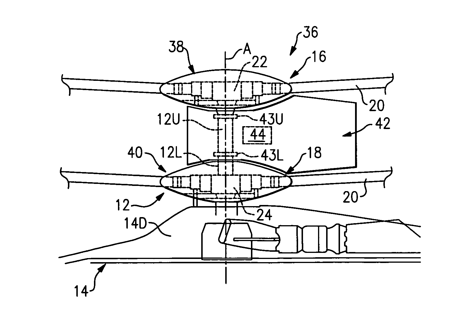
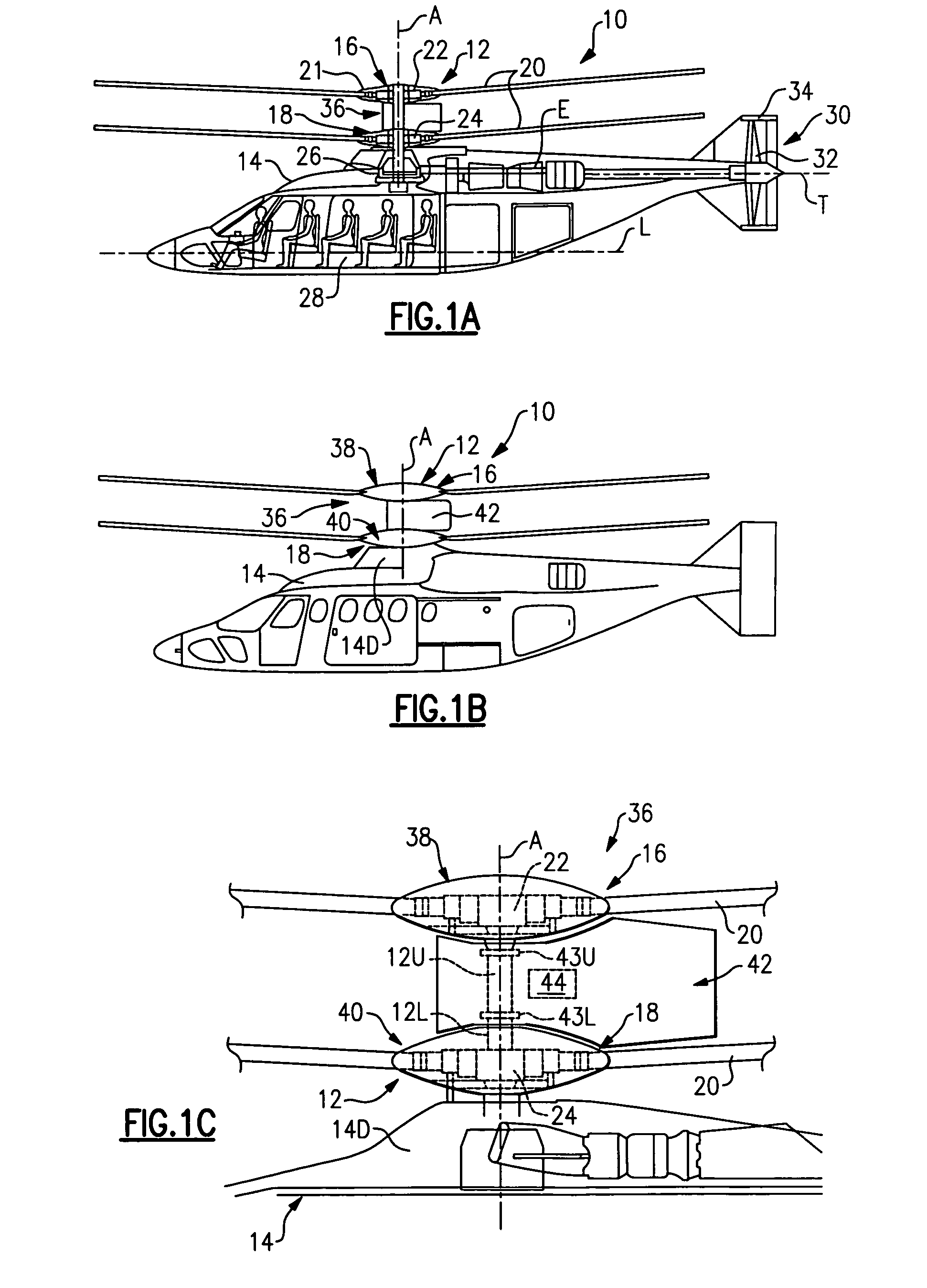
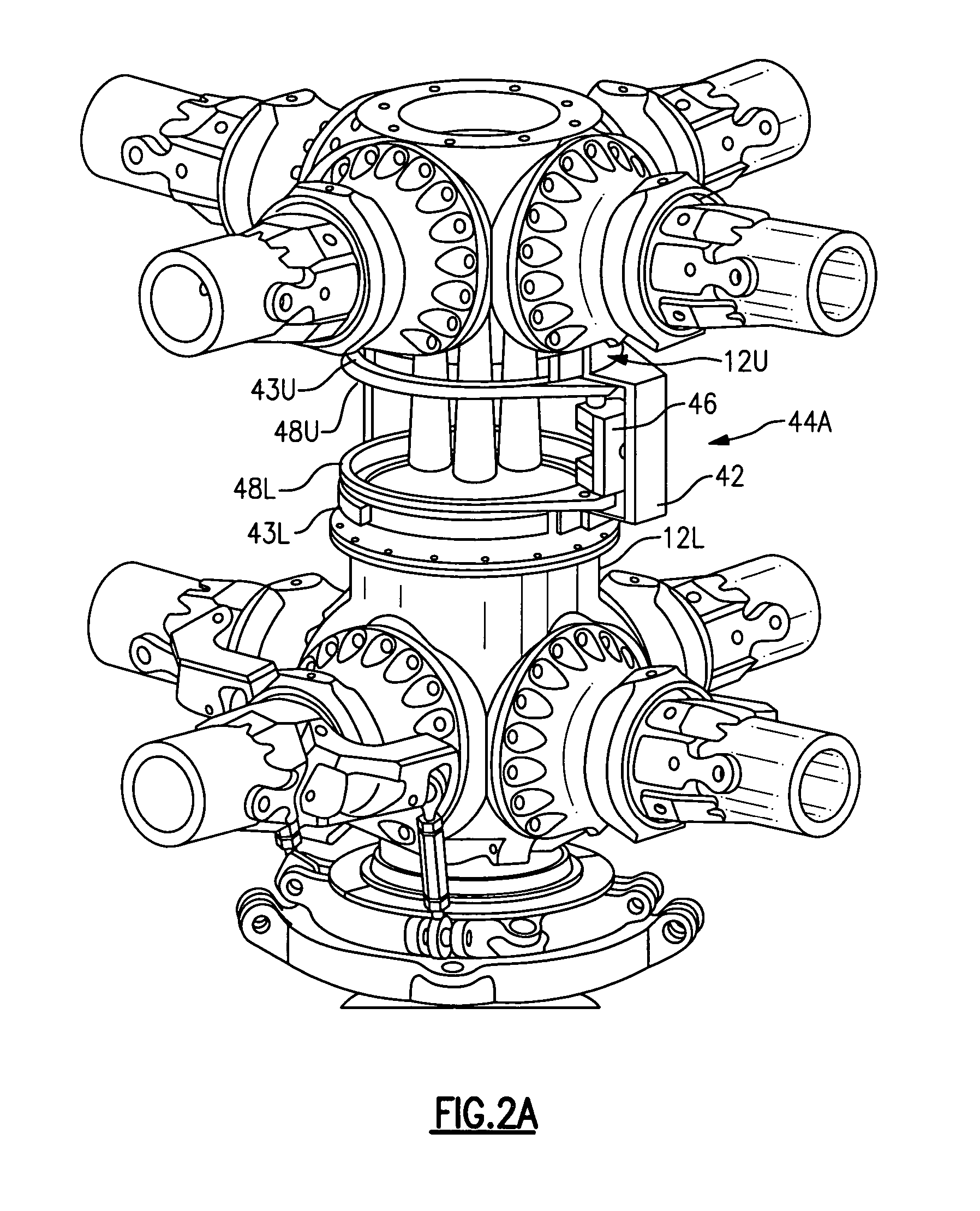
[0009]A rotor hub fairing system for a dual, counter-rotating, coaxial rotor system according to the present invention generally includes an upper hub fairing, a lower hub fairing and a shaft fairing located therebetween. The rotor hub fairing system is attached to the counter-rotating, coaxial rotor system through a bearing arrangement such that the shaft fairing may be rotationally positioned at an azimuthal position about a main rotor axis of rotation relative the airframe by a de-rotation system. The de-rotation system controls the position of the shaft fairing about the axis of rotation such that the shaft fairing is prevented from rotating freely in unison with either rotor shaft as may otherwise result.
[0010]One de-rotation system includes a belt driven system which self-aligns whenever the aircraft reaches a forward flight speed at which the airflow force is greater than the friction force between the belts and pulleys of the de-rotation system. This permits the de-rotation system to be designed for lower loads and thereby provides a light weight system.
[0012]Another de-rotation system may additionally be operated in response to a control system through which the azimuthal position of the shaft fairing can be actively varied throughout all flight profiles. The de-rotation system generally includes a variable torque generator system, a controller in communication with the variable torque generator system and a shaft fairing position sensor in communication with the controller. The de-rotation system may also communicate with a flight control system to selectively azimuthally position the shaft fairing relative the airframe throughout all flight profiles to, for example, increase the maneuverability of the aircraft.

Problems solved by technology

For high-speed rotary wing aircraft, the increased drag resulting from the counter-rotating, coaxial rotor system may result in a relatively significant power penalty.
The interconnecting main rotor shaft between the upper rotor hub assembly and the lower rotor hub assembly, however, is typically exposed.
During hover and low speed maneuvers, however, frictional forces acting on the bearing arrangement may tend to cause the shaft fairing to undesirably rotate in unison with the main rotor system.
Rotation of the shaft fairing may increase drag and reduce the low-observability benefits of the contoured shaft fairing.

Method used


Image

  • De-rotation system for a counter-rotating, coaxial rotor hub shaft fairing
  • De-rotation system for a counter-rotating, coaxial rotor hub shaft fairing
  • De-rotation system for a counter-rotating, coaxial rotor hub shaft fairing

Examples


Embodiment Construction

[0031]FIGS. 1A and 1B illustrate an exemplary vertical takeoff and landing (VTOL) rotary-wing aircraft 10 having a dual, counter-rotating, coaxial rotor system 12 which rotates about an axis of rotation A. The aircraft 10 includes an airframe 14 which supports the dual, counter rotating, coaxial rotor system 12 as well as an optional translational thrust system 30 which provides translational thrust generally parallel to an aircraft longitudinal axis L. Although a particular aircraft configuration is illustrated in the disclosed embodiment, other counter-rotating, coaxial rotor systems will also benefit from the present invention.

[0032]The dual, counter-rotating, coaxial rotor system 12 includes an upper rotor system 16 and a lower rotor system 18. Each rotor system 16, 18 includes a plurality of rotor blades 20 mounted to a rotor hub 22, 24 for rotation about a rotor axis of rotation A. A plurality of the main rotor blades 20 project substantially radially outward from the hub asse...


PUM


Abstract

A rotor hub fairing system includes an upper hub fairing, a lower hub fairing and a shaft fairing therebetween. The rotor hub fairing system is attached to the counter-rotating, coaxial rotor system through a bearing arrangement such that the shaft fairing may be positioned at an azimuthal position about the main rotor axis of rotation relative the airframe by a de-rotation system. The de-rotation system controls the position of the shaft fairing about the axis of rotation such that the shaft fairing is prevented from rotating freely in unison with either shaft as may otherwise result during some flight regimes.

Description

[0001]The present application claims priority to U.S. Provisional Patent Application Ser. Nos. 60 / 693,592, filed Jun. 24, 2005; 60 / 684,694, filed May 26, 2005; and 60 / 776,278, filed Feb. 23, 2006.BACKGROUND OF THE INVENTION[0002]The present invention is directed to a rotor hub fairing system for a rotary-wing aircraft having a counter-rotating, coaxial rotor system, and more particularly, to a de-rotation system which rotationally stabilizes a shaft fairing mounted between an upper hub fairing and a lower hub fairing.[0003]Typically, the aerodynamic drag associated with a rotor hub on a rotary wing aircraft is a significant portion of the overall aircraft drag, typically 25% to 30% for conventional single-rotor helicopters. The rotor system drag increases for a rotary wing aircraft having a counter-rotating, coaxial rotor system primarily due to the dual rotor hubs and the interconnecting shaft therebetween. For high-speed rotary wing aircraft, the increased drag resulting from the ...

Claims


Application Information

Patent Timeline
Patent Type & Authority Patents(United States)
IPC IPC(8): B64C27/00
CPCB64C1/00B64C7/00B64C27/12B64C27/14B64C27/10B64C27/04G01S1/08B64C27/20
Inventor DARROW, JR., DAVID A.BERTOLOTTI, FABIO P.SBABO, THOMAS L.D'ANNA, FRANK P.
Owner SIKORSKY AIRCRAFT CORP
Why Eureka
Try Eureka