Supercharge Your Innovation With Domain-Expert AI Agents!

Continuously variable transmission

a transmission and continuously variable technology, applied in the field of transmission systems, can solve the problems of increasing torque, reducing efficiency, and not using traction drives, and achieves the effects of reducing apparent effects, facilitating manipulation of subjective feelings of the rider to the transmission, and high efficiency

Inactive Publication Date: 2009-12-01
BHSCI
View PDF26 Cites 5 Cited by
  • Summary
  • Abstract
  • Description
  • Claims
  • Application Information

AI Technical Summary

Benefits of technology

"The present invention provides a mechanical continuously variable transmission (CVT) that overcomes the problems of conventional transmissions, such as rough operation, limited shifting, and limited speed range. The invention includes a torque-split mechanism and a control mechanism for smooth operation and easy shifting. The invention also includes a clutch mechanism that selectively connects the torque-split mechanism to an output, allowing for smooth shifting and a wide range of gear ratios. The invention can be used in various vehicles, such as bicycles, wheelchairs, and aircraft, and can be powered by a prime mover, including human power. The technical effects of the invention include smooth operation, easy shifting, and a wide range of gear ratios."

Problems solved by technology

This can be particularly challenging when the input to the transmission, such as torque and speed input, has a cyclic variation, such as that generated by a rider pedaling a bicycle crank.
Efficiency, however, decreases with increased torque due to micro-slip.
Also, traction drives are not used in situations where a shifting between gear ratios occurs often.
The primary disadvantage of continuously variable traction drives is that they must rely upon friction for their operation.
Gear teeth cannot be used because of the continuously variable geometry during shifting of the gear ratio.
The high normal pressure required to develop useful traction results in heavy parts to take the loads.
In some cases, input gearing is used to increase internal speeds and reduce required traction, but at the expense of efficiency losses in the additional gear meshes.
The use of metals, which are very stiff, also requires the parts to be made with very high precision, like a rolling element bearing, leading to high cost of manufacture.
Finally, the very stiff material used and the variable geometry of rolling introduces relative sliding between parts and resulting wear.
Indeed, the inventions of the exemplar patents mentioned above are not currently on the market, probably for these reasons.
However, conventional traction drives suffer from weight problems due to the need to react high normal loads that are necessary to generate traction.
While these drives offer advantages such as low “stutter” (such as vibrations caused from torque feedback due to the cyclic variations at a different frequency from the input rotation), high efficiency, a compact space, large gear ranges, and may be automated for torque response, they also have the drawbacks of high contact loads requiring heavy parts, inability to shift at zero speed, and low shifter force and feedback in shifting the toroidal traction drive.
While these designs offer little stutter, are compact and efficient, and may be automated and have large gear ranges, they generally have high contact loads that require heavy parts, cannot shift at zero speed, and have low shifter force and feedback.
These designs suffer from not having a robust third member to react the normal forces.
However, these designs have high contact stresses compared to other designs and cannot shift at zero speed.
The former is widely used for industrial purposes and uses an inclined cone against a cylindrical ring with traction load transmission, the ring moving axially along the cone to change the gear ratio, resulting in low stutter and high efficiency.
However, this design is too large for a bicycle and has complex shifting mechanisms, limited ratios of gearing, and an inability to shift at zero speed.
The latter utilizes discs to transmit a load by multiple balls, which provides load sharing and lower contact stresses, thus achieving simplicity, low part count, and a more simple shifter, but requiring offset shafts that are large, having an inability to shift at zero speeds, and a low efficiency due to ball carrier friction.
While this design shows promise for applications to bicycles, it also suffers from high contact loads, and an inability to shift at zero speed.
Many methods have been proposed to mitigate the variation, typically involving complex mechanisms that do not eliminate the variation completely.
The disadvantage of this attempt is that the instantaneous matching of speed at the maximum relative velocity between the parts creates a very large force in addition to the useful torque being transferred between the ratchet and the pawl.
This can result in unevenness in the output, and it increases wear on the parts, requiring heavier and more costly drive train components.

Method used


Image

  • Continuously variable transmission
  • Continuously variable transmission
  • Continuously variable transmission

Examples


Embodiment Construction

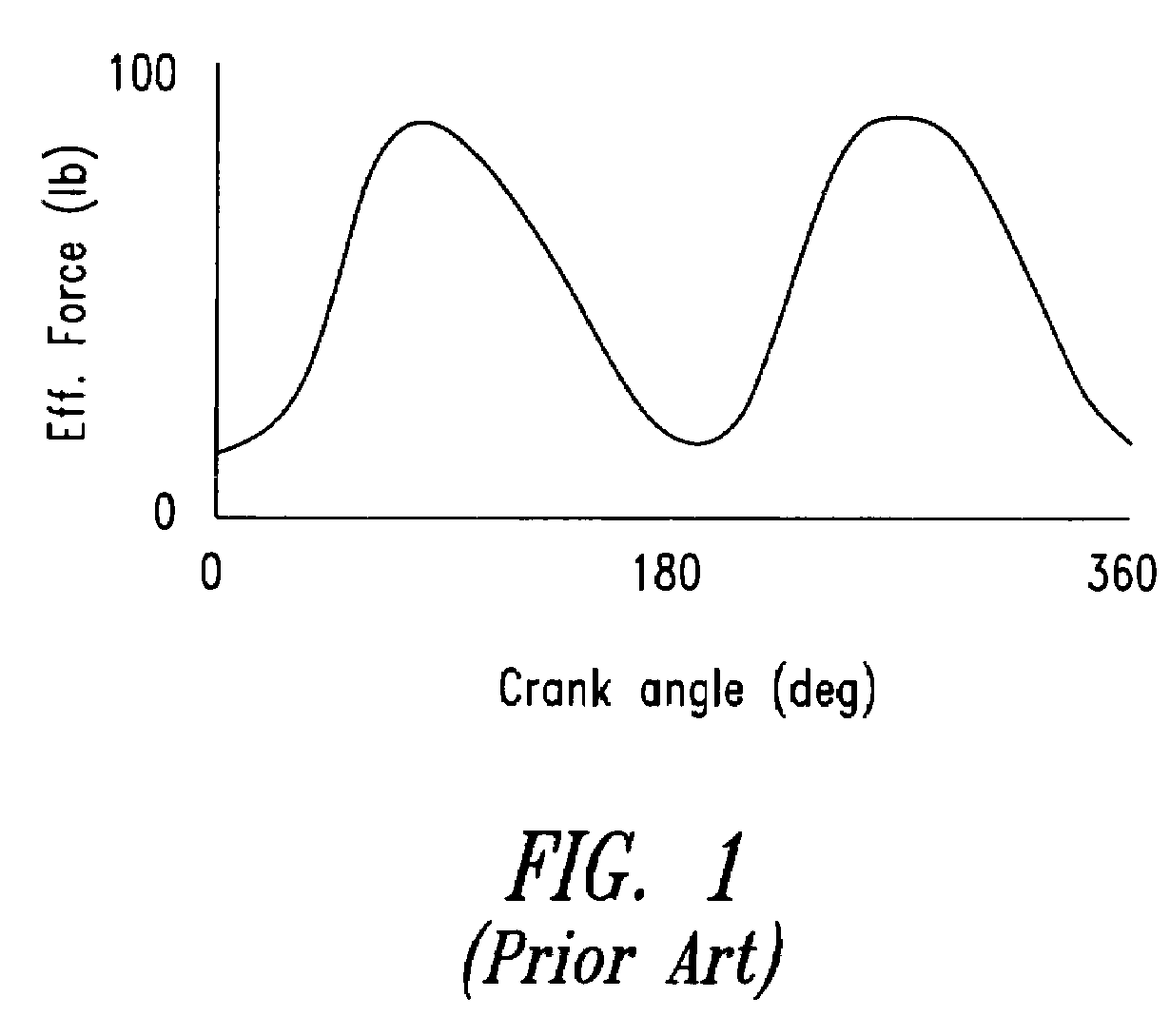
[0058]The disclosed embodiments of the present invention are suited for human-powered vehicles, such as bicycles, having a rotary input. It is to be understood that while the embodiments of the invention are described in the context of human-powered bicycles, they will have application to other devices receiving rotary input in the form of the approximately sinusoidal input force depicted in FIG. 1.

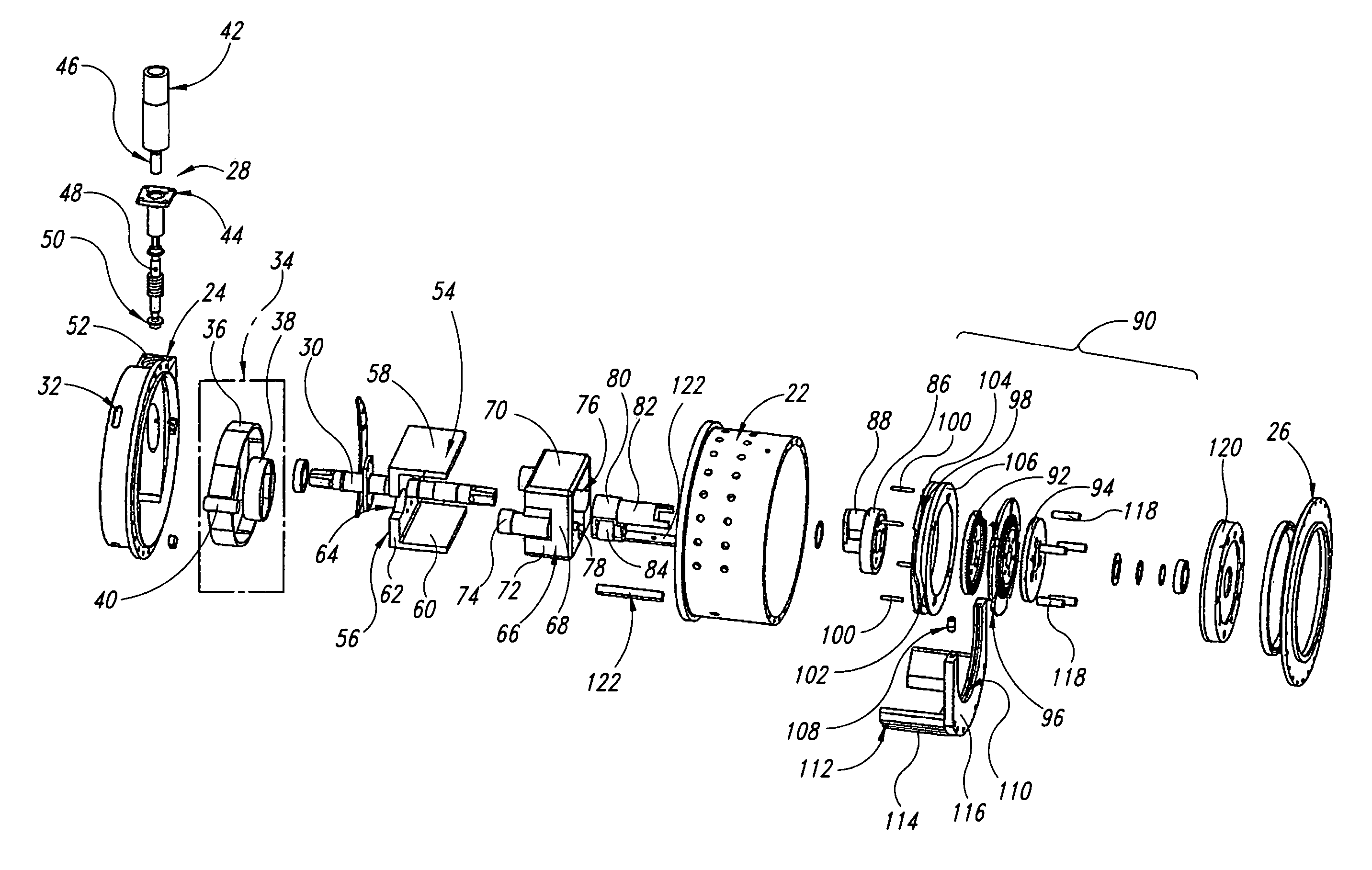
[0059]All of the embodiments of the present invention function as a full-wave rectifier, the clutch acting as the rectifying elements and smoothing out the pseudo-sinusoidal torque input at each complete cycle of applied torque that is generated by one stroke of a human prime mover. In one embodiment, concentric shafts counter-rotate with respect to each other by the action of a shuttle or rocker arms reacting to the motion imposed on them by a cam interacting with cam followers. The clutches on the output ends of the concentric shafts only transmit motion in one direction (forward) there...


PUM


Abstract

A torque transfer mechanism for use as a continuously variable transmission that includes an input shaft, a cam member, a torque-splitting mechanism cooperating with the cam member, and a torque output assembly for coupling the torque splitting mechanism to an output shaft when there is substantially zero relative velocity between the moving parts to be disconnected to minimize torque feedback to the input shaft.

Description

BACKGROUND OF THE INVENTION[0001]1. Technical Field[0002]The present invention pertains to a transmission system, and more particularly to a mechanical continuously variable transmission particularly suited for human-powered vehicles.[0003]2. Description of the Related Art[0004]Continuously variable speed transmissions are used for power and rotational motion transmission in a variety of applications where continuous variation of input to output ratio is beneficial. Variable speed transmissions attempt to provide for a seamless transition throughout the available speed range. This can be particularly challenging when the input to the transmission, such as torque and speed input, has a cyclic variation, such as that generated by a rider pedaling a bicycle crank.[0005]The torque and speed input to the pedals of a bicycle vary at twice the frequency of the pedaling rotation with an approximately sinusoidal waveform. The relationship between average pedal RPM and bicycle speed on a stan...

Claims


Application Information

Patent Timeline
Patent Type & Authority Patents(United States)
IPC IPC(8): F16H21/00B62M9/08B62M11/06B62M25/08F16H27/00F16H29/04F16H29/18F16H29/20F16H35/02
CPCB62M11/06F16H29/04F16H29/20Y10T74/1518Y10T74/1836Y10T74/1503
Inventor PARKS, ALBERT HAROLDZHENG, NING
Owner BHSCI
Features
  • R&D
  • Intellectual Property
  • Life Sciences
  • Materials
  • Tech Scout
  • Unparalleled Data Quality
  • Higher Quality Content
  • 60% Fewer Hallucinations
Learn More