Delay stage, ring oscillator, PLL-circuit and method

a technology of ring oscillator and delay stage, which is applied in the field of delay stage, can solve the problems of wide frequency ranges that are not or are not acceptable throughout, ring oscillators are generally deemed overly unstable and subject to frequency drift, and can be difficult to achieve the effect of achieving the effect of reducing the frequency drift of the oscillator

Active Publication Date: 2009-12-08
INFINEON TECH AG
View PDF9 Cites 19 Cited by
  • Summary
  • Abstract
  • Description
  • Claims
  • Application Information

AI Technical Summary

Problems solved by technology

However, by way of example, in a CMOS based ring oscillator currently being manufactured as part of a CMOS IC chip, the difference in frequency of the oscillator of one chip from the frequency of the oscillator of another supposedly identical chip can be rather great.
Therefore, where precise timing is required, e. g. frequency accuracy, to within a few percent, such wide frequency ranges are not or not throughout acceptable.
Because of the above mentioned variations, ring oscillators have generally been deemed overly unstable and subject to frequency drift.
The large variation in the oscillator gain causes an unwanted large variation in the PLL-bandwidth.
However, frequency dividers for high frequencies usually consume more power than frequency dividers which are designed for lower frequencies.

Method used


Image

  • Delay stage, ring oscillator, PLL-circuit and method
  • Delay stage, ring oscillator, PLL-circuit and method
  • Delay stage, ring oscillator, PLL-circuit and method

Examples


Embodiment Construction

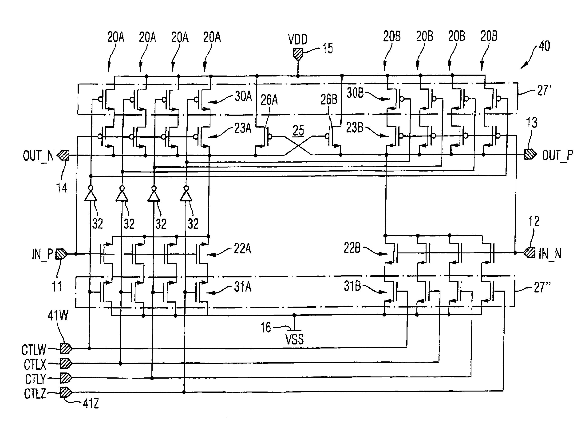
[0022]According to one embodiment, a voltage controlled oscillator (VCO) is provided which shows a programmable oscillation frequency range and a programmable gain of the oscillator by programming its delay stages.

[0023]According to another embodiment of the delay stage, the capacitive load at the output of this delay stage typically is constant. To switch between different oscillation frequency ranges and gains of the voltage controlled oscillator parallel delay branches inside the stage are typically digitally switched on or switched off to increase or decrease, respectively, the gain of the delay stage and, thus, increase or decrease, respectively, the oscillation frequency of the oscillator. With this implementation, only the delay branches that are turned on and which are connected to the supply voltage are consuming power. The power consumption and the oscillation frequency is therefore highly linear proportional to the number of activated delay branches within the delay stage...


PUM


Abstract

A delay stage for a semiconductor device includes at least one delay branch and at least one controllable switching apparatus. The at least one controllable switching apparatus is configured to connect a predefined amount of the at least one delay branch to a supply voltage.

Description

BACKGROUND OF THE INVENTION[0001]The present invention relates to a delay stage for a semiconductor device. The invention further relates to a ring oscillator, a PLL-circuit and a method for operating the delay stage.[0002]A typical delay circuit delivers an output pulse at some predetermined delay time after receiving an input pulse. The predetermined delay period, that is the period between the input and output pulses, must be accurate and repeatable. Those delay circuits comprise a delay stage especially for use in a semi-conductor device, such as an oscillator.[0003]There are numerous electronic circuit applications where, for proper operation, it is necessary to provide precise timing or synchronization of one portion of the circuit with another one. Such timing is conveniently provided by an oscillator whose frequency is sufficiently accurate for the requirements of the circuit being timed or synchronized. Depending on the degree of accuracy required, an oscillator may be very...

Claims


Application Information

Patent Timeline
Patent Type & Authority Patents(United States)
IPC IPC(8): H03K3/03
CPCH03F3/45237H03L7/0995H03K3/0315H03K3/356113H03K5/133H03F3/45475H03F2203/45138H03F2203/45236H03F2203/45318H03F2203/45352H03F2203/45366H03F2203/45652H03K2005/00071H03K2005/00208H03K2005/00215H03K2005/00228H03K2005/0028
Inventor THALLER, EDWIN
Owner INFINEON TECH AG
Why Eureka
Try Eureka