Voltage controlled oscillator circuit and method

a voltage control and oscillator technology, applied in the direction of oscillator, pulse generator, pulse technique, etc., can solve the problems of oscillator noise in the supply, oscillator and the oscillator is susceptible to noise in the power supply

Inactive Publication Date: 2003-12-18
IBM CORP
View PDF4 Cites 24 Cited by
  • Summary
  • Abstract
  • Description
  • Claims
  • Application Information

AI Technical Summary

Benefits of technology

0015] FIG. 2 shows a schematic circuit diagram of a low volta

Problems solved by technology

However, since the supply to the oscillator is used to tune the oscillator, the connection of a following stage to the oscillator is compromised, the tuning of the oscillator is subject to noise in the supply, and the oscillator supply is not easily decoupled from the chip supply.
However, this oscillator is susceptible to noise in the power suppl

Method used


Image

  • Voltage controlled oscillator circuit and method
  • Voltage controlled oscillator circuit and method
  • Voltage controlled oscillator circuit and method

Examples


Embodiment Construction

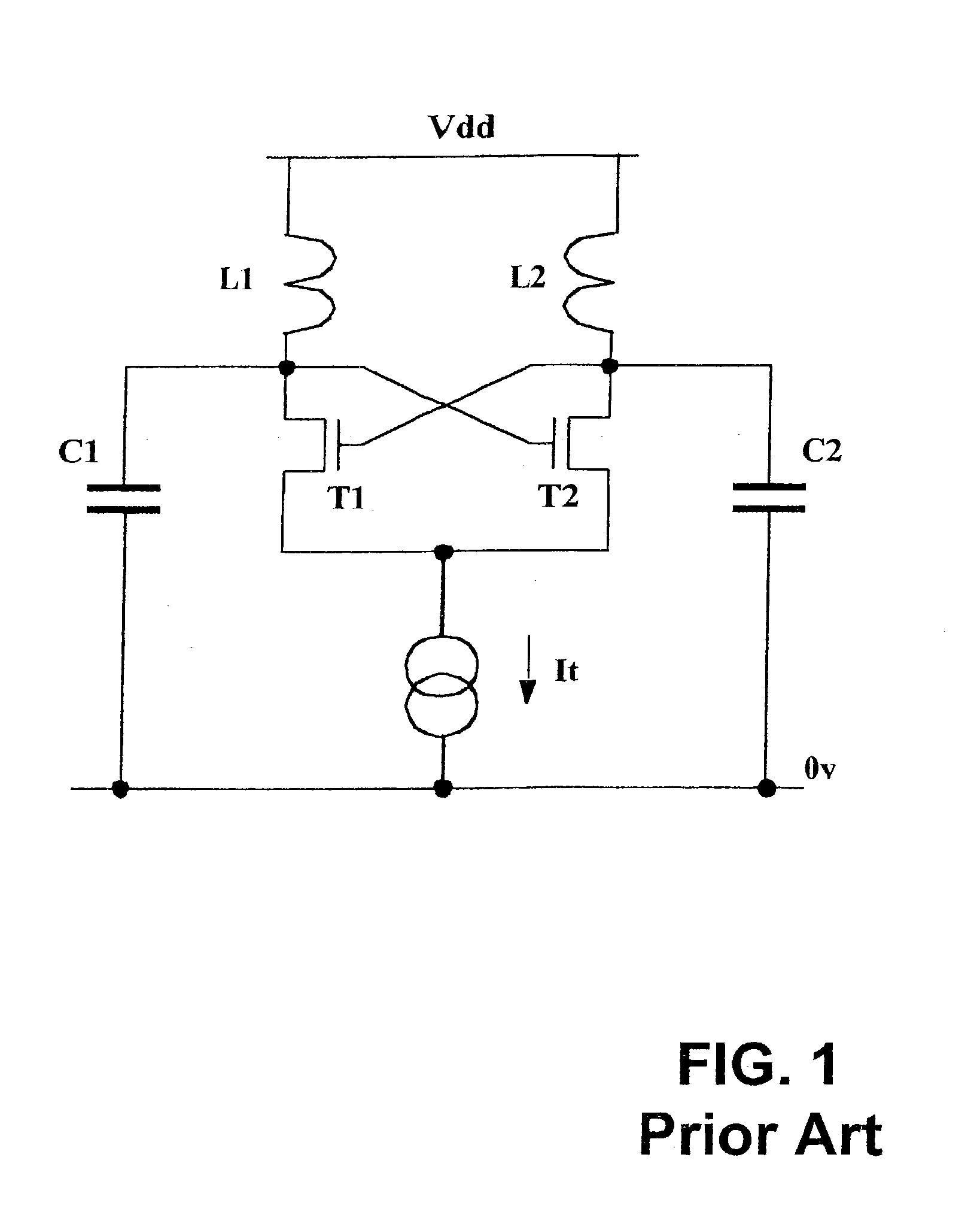
[0018] Referring firstly to FIG. 1, a conventional harmonic oscillator circuit as shown comprises a cross-coupled NFET (N-channel Field Effect Transistor) pair T1 and T2, biased with a tail current source It, which provides a negative resistance element which counteracts the losses within an LC tank circuit formed by L1, C1 and L2, C2 (principally the self resistance of the inductors L1 and L2). When the conditions have been achieved for oscillation, the circuit will oscillate at a frequency given by the resonant frequency of the inductor and capacitor combination. This circuit is well known and is generally used to implement harmonic oscillator designs. It is also possible to replace the capacitors C1 and C2 with a single capacitor connected between the drains of the transistor pair T1 and T2. During oscillation, the voltage at the nodes which connect the inductor to the NFET drain will oscillate around the supply voltage Vdd. The amplitude of oscillation is set by the level to whi...


PUM


Abstract

A voltage controlled oscillator circuit and method comprising: a harmonic oscillator having a cross-coupled NFET devices (T1, T2) and an LC tank circuit (L1, L2, C) performing oscillation; a series voltage regulator (210) regulating voltage applied to the harmonic oscillator via a PFET device (T3) and differential amplifier (R); and a tuning circuit (220) having voltage controlled capacitance 'Zero-Vt' NFET devices (T4, T5) controlling oscillation of the harmonic oscillator. A differential output buffer (B) provides output buffering to a subsequent stage. This provides advantages that: operation at low supply voltages is facilitated and the sensitive oscillator cell is decoupled from the main supply noise offering improved phase noise performance; the output swing of the oscillator has a well controlled common-mode value which can be selected to most efficiently drive a following stage; and using 'Zero-Vt' NFETs facilitates the use of a lower supply voltage.

Description

[0001] This invention relates to voltage controlled oscillators, and particularly to such oscillators which can be directly integrated into a CMOS (Complementary Metal Oxide Semiconductor) integrated circuit (IC) and which will oscillate at high frequency.[0002] In the field of this invention that high frequency voltage controlled oscillators are commonly used in RF (Radio Frequency) circuit design. The standard `harmonic oscillator` used in this invention is well known in the literature. However this invention addresses the problems of operating the circuit at low voltage (required for modern CMOS chips) and provides a technique for biasing the output so that it can be conveniently used by following circuitry.[0003] From U.S. Pat. No. 6,225,871 there is known a voltage controlled CMOS oscillator in which the frequency of oscillation of two cross-coupled CMOS inverters with a parallel LC tank circuit connected between the two drains can be varied by a control voltage which varies th...

Claims


Application Information

Patent Timeline
IPC IPC(8): H03B5/12
CPCH03B5/1228H03B5/1253H03B5/1215
Inventor MASON, JAMES STEPHEN
Owner IBM CORP
Why Eureka
Try Eureka