System and method for clock signal synchronization

a clock signal and clock signal technology, applied in the field of system and method for clock signal synchronization, can solve the problems of increasing the cost of communication circuit, not being available in modern applications, and high cost of crystal oscillator

Inactive Publication Date: 2007-07-12
APEXONE MICROELECTRONICS
View PDF3 Cites 21 Cited by
  • Summary
  • Abstract
  • Description
  • Claims
  • Application Information

AI Technical Summary

Benefits of technology

[0032] By now it should be appreciated that a system and a process for synchronizing or locking a clock signal to a data signal have been provided. The synchronization system in accordance with present invention can include a simple and cost efficient RC oscillator and simple digital circuitry. Such a system has the qualities of small chip size, reliable operation, and cost efficiency. The synchronization process in accordance with the present invention involves only digital operations that can be achieved in only one hand shake. Therefore, it is simple, fast, reliable, and unsusceptible to variations in chip fabrication processes and operation conditions.

Problems solved by technology

The crystal oscillator is expensive.
The internally based timer typically requires long training sequences to tune a PLL or DLL, which may not be available in modern applications, such as universal serial bus (USB) applications.
The ICO or VCO is an application specific integrated circuit (ASIC) that takes a large chip area and thereby increases the cost of the communication circuit.
The analog multiple step tuning process is slow and complicated.
The performance of the analog tuning circuit is susceptible to process and temperature variations.

Method used


Image

  • System and method for clock signal synchronization
  • System and method for clock signal synchronization
  • System and method for clock signal synchronization

Examples


Embodiment Construction

[0009] Various embodiments of the present invention are described herein below with reference to the figures, in which elements of similar structures or functions are represented by like reference numerals throughout the figures. It should be noted that the figures are only intended to facilitate the description of the preferred embodiments of the present invention. They are not intended as an exhaustive description of the present invention or as a limitation on the scope of the present invention.

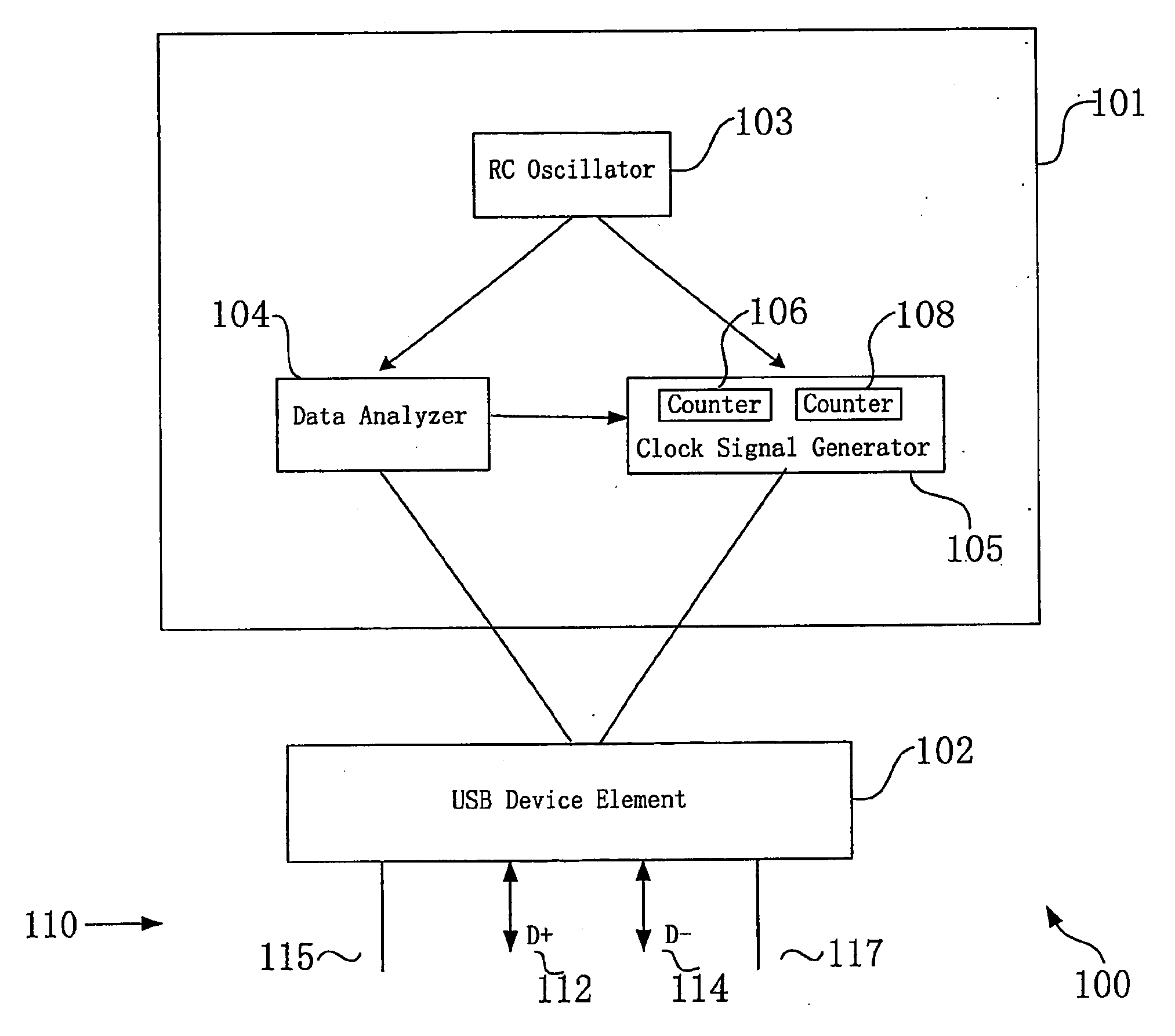
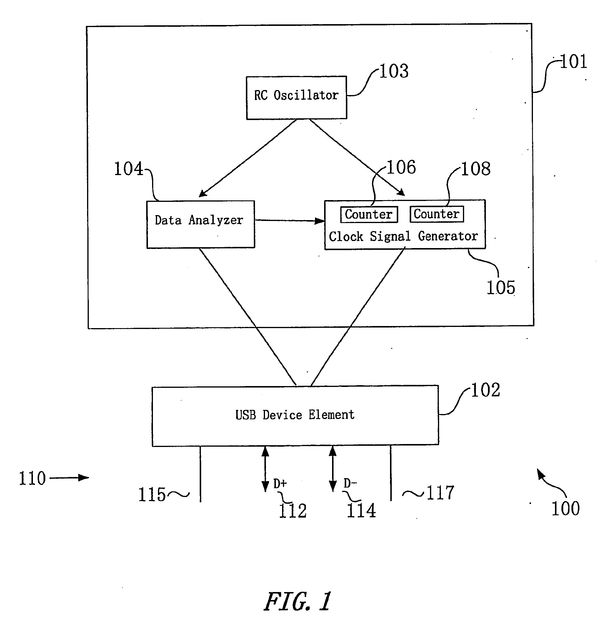
[0010]FIG. 1 is a block diagram illustrating a precision timing component or a clock signal synchronization system 101 in accordance with the present invention. By way of example, FIG. 1 shows system 101 is a part of a universal serial bus (USB) device 100 and functions for generate a clock signal synchronized with a packet received from a host (not shown in FIG. 1) via a USB bus 110. In FIG. 1 an element 102 represents portions of USB device 100 other than clock signal synchronization sys...


PUM


Abstract

A system (101) for clock signal synchronization includes a data analyzer (104) and a synchronized clock signal generator (105) coupled to an RC oscillator (103). The data analyzer (104) generates a digital control signal representing the number of cycles of a reference signal of the RC oscillator (103) during an eight-bit period of an incoming token packet. The synchronized signal clock generator (105) uses the digital control signal to lock a clock signal to packets that have the same bit rate as the token packet.

Description

FIELD OF THE INVENTION [0001] The present invention relates, in general, to a system and method for signal synchronization and, more particularly, to a system and a method for locking the clock signal of an oscillator to a data stream in data communications. BACKGROUND OF THE INVENTION [0002] Conventional data communication circuits require a precision timing component to provide a reference frequency clock signal to an external device that is coupled via a signal transmission bus to a host. A precision timing component in such communication circuits usually includes a crystal oscillation element. An internally based timer tunes the clock signal of the crystal oscillation element to match the clock signal to the incoming data stream from the host. Typically, a phase lock loop (PLL) or a delay lock loop (DLL) in the timer serves the functions of tuning and locking the clock signal through data training, phase shifting, phase selection, or the like. The crystal oscillator is expensive...

Claims


Application Information

Patent Timeline
Patent Type & Authority Applications(United States)
IPC IPC(8): H03L7/00
CPCH04L7/042
Inventor MA, QINGJIANGGAO, JAMES Y.REN, YONGQING
Owner APEXONE MICROELECTRONICS
Why Eureka
Try Eureka