
Dual-axis scanning system and method

a scanning system and dual-axis technology, applied in the field of image acquisition systems and image processing techniques, can solve the problems of inefficient system design and operation, high cost and general difficulty in implementation, and inconvenient design and operation of systems, etc., to achieve rapid determination of object locations, without excessive cost

Active Publication Date: 2009-12-15
ONTO INNOVATION INC
View PDF26 Cites 19 Cited by
  • Summary
  • Abstract
  • Description
  • Claims
  • Application Information

AI Technical Summary

Benefits of technology

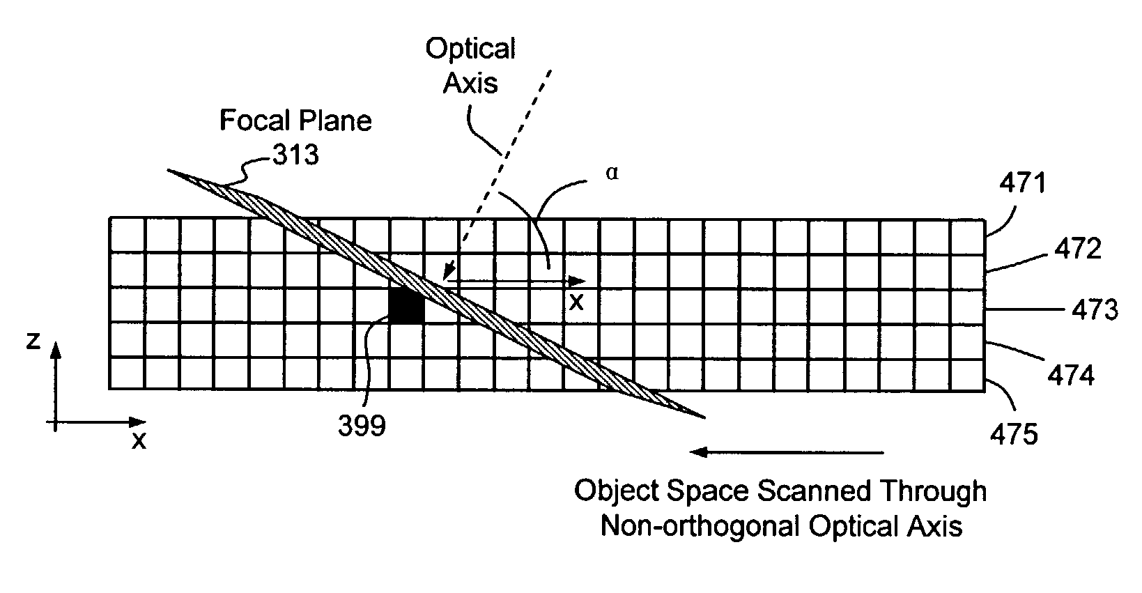
[0008]Embodiments of the present invention overcome the above-mentioned and various other shortcomings of conventional technology, providing an image acquisition system and method employing a non-orthogonal optical axis. As set forth in detail below, a system and method of dual-axis scanning allow rapid determination of object locations in three-dimensional space without excessive costs.

Problems solved by technology

Traditional image acquisition and processing methods such as deconvolution and tomography, for example, are computationally expensive and generally difficult to implement; conventional optical methods such as confocal microscopy are expensive and slow.
Conventional systems such as those illustrated and described with reference to FIGS. 1 and 2 are difficult to implement, require complicated instrumentation and very precise motion control systems, and generally capture more images than necessary; accordingly, such systems are inefficient and unnecessarily expensive to design and operate.

Method used


Image

  • Dual-axis scanning system and method
  • Dual-axis scanning system and method
  • Dual-axis scanning system and method

Examples


Embodiment Construction

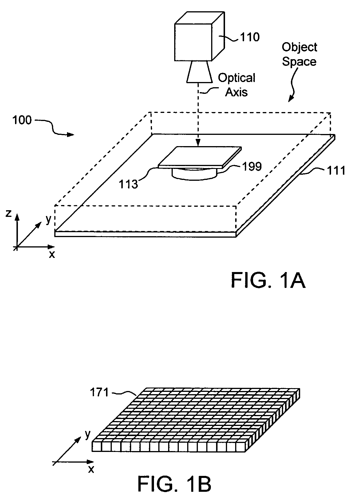
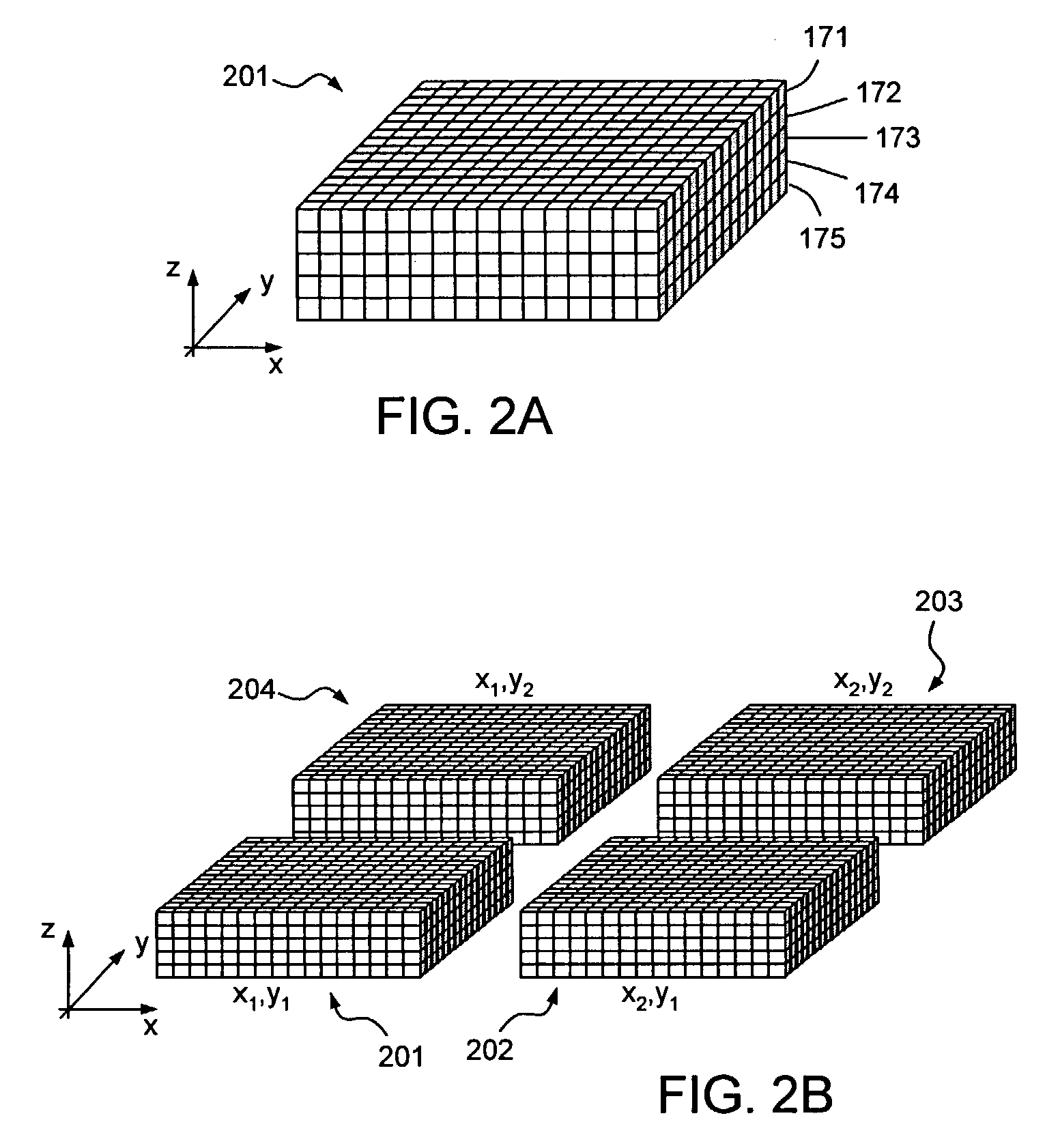
[0027]As set forth above, FIG. 1A is a simplified functional block diagram illustrating one embodiment of a conventional image acquisition system, and FIG. 1B is a simplified block diagram illustrating an image captured by the system of FIG. 1A. The goal of such systems is to generate stacks of images; each stack is composed of a series of images acquired at successive z locations in the object space. In that regard, FIGS. 2A and 2B are simplified block diagrams illustrating image stacks acquired by conventional imaging systems.

[0028]To acquire the data illustrated in FIG. 2B, a conventional system must collect twenty discrete images (ie., five images 171-175 for each of four stacks 201-204). Assuming video rate acquisition performance and similar component movement rates and settling time, then the time required to acquire these images may be estimated by the following equation:

Time=(Total Frames)×(Exposure+Movement+Settling)

[0029]For twenty frames, this equation yields a time of a...


PUM


Abstract

An image acquisition system and method may employ a non-orthogonal optical axis. The optical axis may be established in such a manner as to position a focal plane of an imaging device in a selected orientation relative to the object space. Such selective positioning and orientation of the focal plane allows the integration of two coordinate axes and enables dual-axis scanning of the object space. In some embodiments, the focal plane may extend throughout the entire depth dimension of the object space.

Description

[0001]This application claims the benefit of U.S. provisional application Ser No. 60 / 346,313 entitled “DUAL-AXIS SCANNING FOR THE LOCALIZATION OF OBJECTS IN THREE-DIMENSIONAL SPACE,” filed Dec. 28, 2001.FIELD OF THE INVENTION[0002]Aspects of the present invention relate generally to image acquisition systems and image processing techniques, and more particularly to an efficient system and method of capturing image data along a non-orthogonal optical axis.DESCRIPTION OF THE RELATED ART[0003]Digital imaging techniques are typically employed to facilitate identification and localization of objects in three-dimensional (3D) space; various techniques have utility in numerous applications and are used in conjunction with, for example, machine vision apparatus, manufacturing and fabrication systems, and inspection tools. Traditional image acquisition and processing methods such as deconvolution and tomography, for example, are computationally expensive and generally difficult to implement;...

Claims


Application Information

Patent Timeline
Patent Type & Authority Patents(United States)
IPC IPC(8): G06K9/00G06T15/00H04N13/00G06T1/00
CPCG06T1/0007
Inventor STROM, JOHN T.
Owner ONTO INNOVATION INC
Learn More