
Controller of doubly-fed induction generator

a doubly-fed induction generator and control device technology, which is applied in the direction of electric generator control, dynamo-electric converter control, dc-ac conversion without reversal, etc., can solve the problem that the power factor of the stator side of the doubly-fed induction generator cannot be directly controlled, the conventional low voltage driving approach has a limit to control the doubly-fed induction generator, and the energy generated from the rotor coil cannot be regenerated

Active Publication Date: 2009-12-29
KOREA ELECTROTECH RES INST
View PDF27 Cites 47 Cited by
  • Summary
  • Abstract
  • Description
  • Claims
  • Application Information

AI Technical Summary

Benefits of technology

The solution effectively controls high voltage doubly-fed induction generators, reduces harmonic distortion, enhances energy efficiency, and ensures stable grid operation by synchronizing stator voltage with grid voltage, enabling fault ride-through and preventing islanding, thus improving the reliability and efficiency of dispersed power generation facilities.

Problems solved by technology

Accordingly, the conventional approach of low voltage driving has a limit to control the doubly-fed induction generator.
However, this approach uses compulsive coupling in terms of hardware while voltage vectors are not synchronized with each other so that an inrush current may occur in the grid coupling step and it is difficult to expect a rapid response.
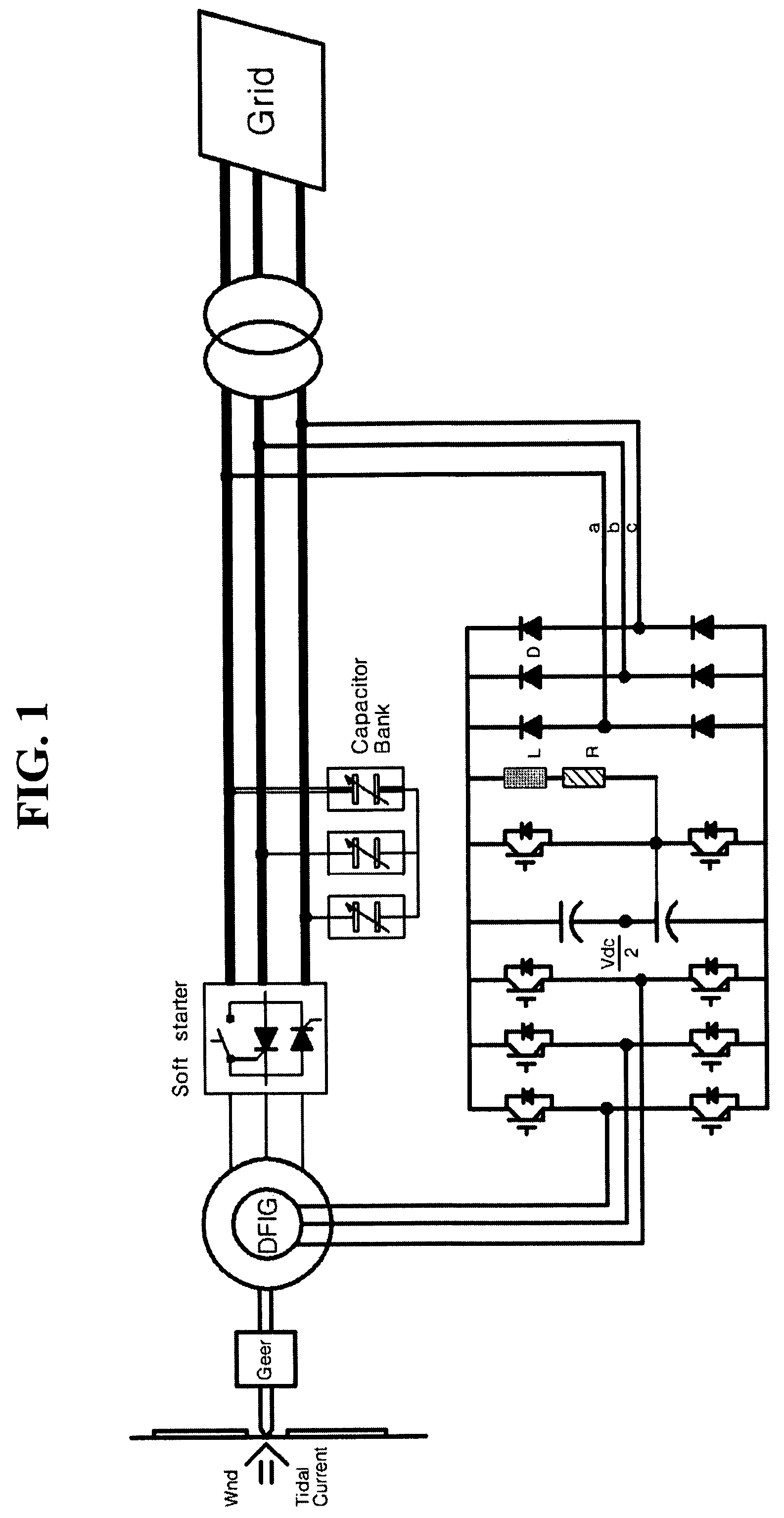
To summarize the disclosed technique to which the present invention is related, the approach disclosed in FIG. 1 (U.S. Pat. No. 6,856,040B2) is applied to more than 95% of the wind power generation systems to which the doubly-fed induction generation is applied, however, it has drawbacks that an energy generated from a rotor coil can not be regenerated toward a grid side and an active power and a power factor of the stator side of the doubly-fed induction generator can not be directly controlled.
However, it disadvantageously has a high voltage distortion factor and is not perfect in terms of grid voltage synchronization, and is required to have an improved technique which can ensure high quality of maintenance and safety of the power grid when the grid is electrically interrupted or shortly interrupted.
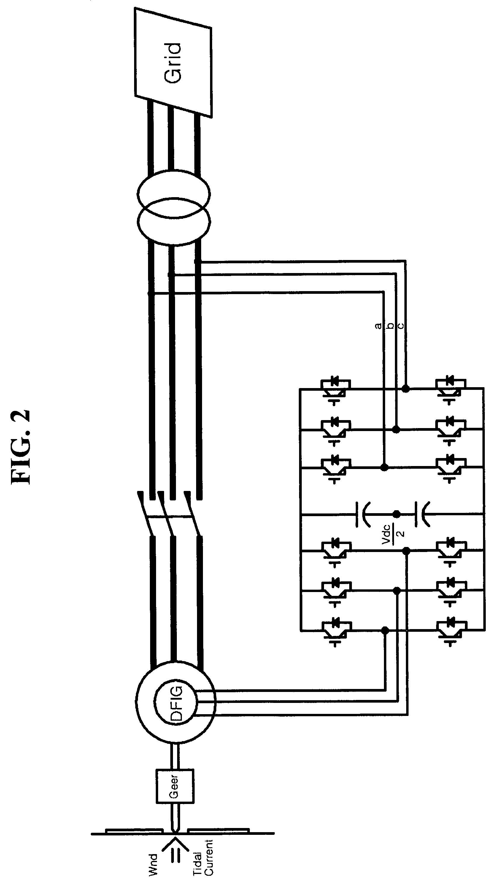
However, this approach has a topology mainly used for controlling a generator having a low voltage specification because it is based on a 3-leg IGBT module, and has a structural drawback that it corresponds to a 2-level converter having only two kinds of line voltage potential of an output voltage so that a distortion factor is very high enough to exceed 10% in a low speed region far from a rated speed.
Such a bad voltage distortion factor becomes worse when a high voltage doubly-fed induction generator having a high voltage specification is driven.
When the generator is controlled by a signal having a significant variation width, the generator may be broken due to breakdown, and a reflective signal may occur all the time when the generator is driven by a control signal from a converter, so that an overlapped result may return to the input side when a voltage distortion factor is high, which limits the spaced distance, usually not more than 20 [m], between the converter and the generator.
When such a method is employed for controlling the doubly-fed induction generator, 0 [Hz] is generated, which results from the difference between a voltage frequency induced to the stator coil and a grid frequency, so that grid coupling can not be made, which leads to degraded doubly-fed induction generator that can not generate a power source from a dispersed power generation facility.
Furthermore, a control algorithm is not yet reported which is developed for having a fault ride-through function, an anti-islanding function and a grid voltage synchronization function which are specifically required when a grid-coupled generator needs to be controlled.

Method used


Image

  • Controller of doubly-fed induction generator
  • Controller of doubly-fed induction generator
  • Controller of doubly-fed induction generator

Examples


Embodiment Construction

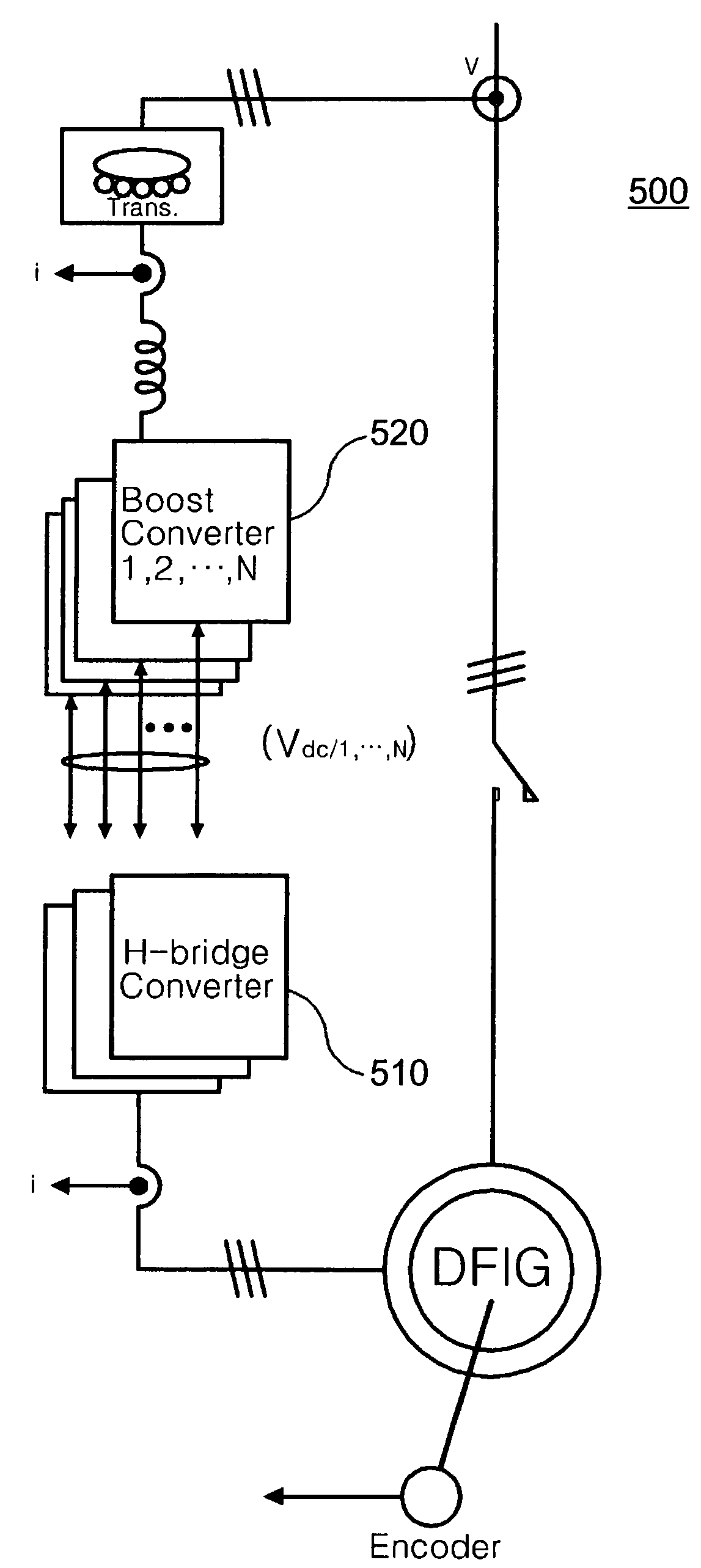
[0051]The present invention relates to a method of controlling a doubly-fed induction generator having a high voltage specification (or a doubly-fed induction motor), whereas the conventional 2-level inverters are designed back-to-back to control the doubly-fed induction generator (U.S. Pat. No. 5,798,631A, WO 2004 / 098261 A2).

[0052]The approach of controlling the doubly-fed induction generator composed of 3-leg IGBTs back-to-back with a signal having a two-level voltage output has a structure capable of transceiving an energy from one direction and the opposite direction so that it can cope with both log voltage specification and high voltage specification. However, it drives the doubly-fed induction generator by generating a voltage waveform having a two-level shape, so that the voltage distortion factor is not good and a voltage variation width (dv / dt) varying in a unit period is inevitably large which often leads to a breakdown of the generator. Accordingly, when the generator ha...


PUM


Abstract

Disclosed is a controller of a grid coupled type doubly-fed induction generator having a multi-level converter topology, which can control the doubly-fed induction generator having a high voltage specification and can perform a fault ride-through function, an anti-islanding function and a grid voltage synchronization function required for a dispersed power generation facility. The controller makes a H-bridge multi-level converter generate a three-phase voltage waveform resulted from the structure that single-phase converters each being composed of a 2-leg IGBT are stacked in a serial manner, and controls a rotor current so as to make the rotor coil of the doubly-fed induction generator in charge of a slip power only. The boost converter is composed of a 3-leg IGBT and a boost inductor generating a direct current voltage of its source required for the H-bridge multi-level converter.

Description

CLAIM OF PRIORITY[0001]This application makes reference to, incorporates the same herein, and claims all benefits accruing under 35 U.S.C. §119 from an application for CONTROLLER OF DOUBLE-FED INDUCTION GENERATOR earlier filed in the Korean Intellectual Property Office on 8 Jun. 2007 and there duly assigned Serial No. 10-2007-0056186.BACKGROUND OF THE INVENTION[0002]1. Field of the Invention[0003]The present invention relates to a doubly-fed induction generator, and in particular, to a controller of a doubly-fed induction generator.[0004]2. Description of the Related Art[0005]A doubly-fed induction generator is a representative type of a generator which shares 50% of a wind power generation system market, and is also researched and developed for tidal current power generation, wave power generation, and hydropower generation. The market for the wind power generation system is rapidly growing enough to exceed 30% annually, and is expected to grow toward the large-scale system in the ...

Claims


Application Information

Patent Timeline
Patent Type & Authority Patents(United States)
IPC IPC(8): H02H7/06H02P9/00F03D9/00H02P9/04H02M7/48
CPCH02M5/4585H02M7/49H02P9/007H02P2207/073H02M2007/4835H02M7/4835H02P9/34
Inventor PARK, JUNG-WOOLEE, KI-WOOKKIM, DONG-WOOK
Owner KOREA ELECTROTECH RES INST
Learn More