Enclosed insulator assembly for high-voltage distribution systems

a technology of enclosed insulators and distribution systems, applied in the direction of air-break switches, electrical equipment, operating/releasing mechanisms of protective switches, etc., can solve the problems of increased operating costs, long installation time or breakage, increased operating costs of utilities, etc., and achieve the effect of preventing corrosion

Inactive Publication Date: 2009-12-29
IMPACT POWER LLC A DELAWARE LLC
View PDF21 Cites 4 Cited by
  • Summary
  • Abstract
  • Description
  • Claims
  • Application Information

AI Technical Summary

Benefits of technology

[0020]By making an enclosed insulator assembly in this fashion, a circuit breaker can be converted to a disconnect switch, and vice-versa, by using the disclosed interchangeable cutout fuse tube assembly or disconnect tube assembly, respectively. In addition, the energized parts are shielded, thus protecting personnel and animals from accidental contact. The O-rings on the fittings inhibit air flow over the contact points, thus preventing corrosion that could weld the contacts together, and impede or prevent safe pulling out of the handle and tube assembly. Furthermore, the load interrupter attached to the bottom of the cutout fuse tube or disconnect tube assemblies provides load break capability.

Problems solved by technology

In congested areas, the height of a utility pole is typically shared by power lines and cables from utilities, communications, and television companies, and increased pole height results in increased operations costs.
Porcelain is heavy and brittle which may cause a long installation time or breakage during transport, handling, or installation.
These cause operating costs to increase for a utility.
Lead is heavy and toxic.
Over time, the enclosed insulator assembly is subjected to a variety of weather conditions and air contamination, causing corrosion to occur between the insulator terminals and tube fittings which make it difficult to remove the bayonet.

Method used


Image

  • Enclosed insulator assembly for high-voltage distribution systems
  • Enclosed insulator assembly for high-voltage distribution systems
  • Enclosed insulator assembly for high-voltage distribution systems

Examples


Embodiment Construction

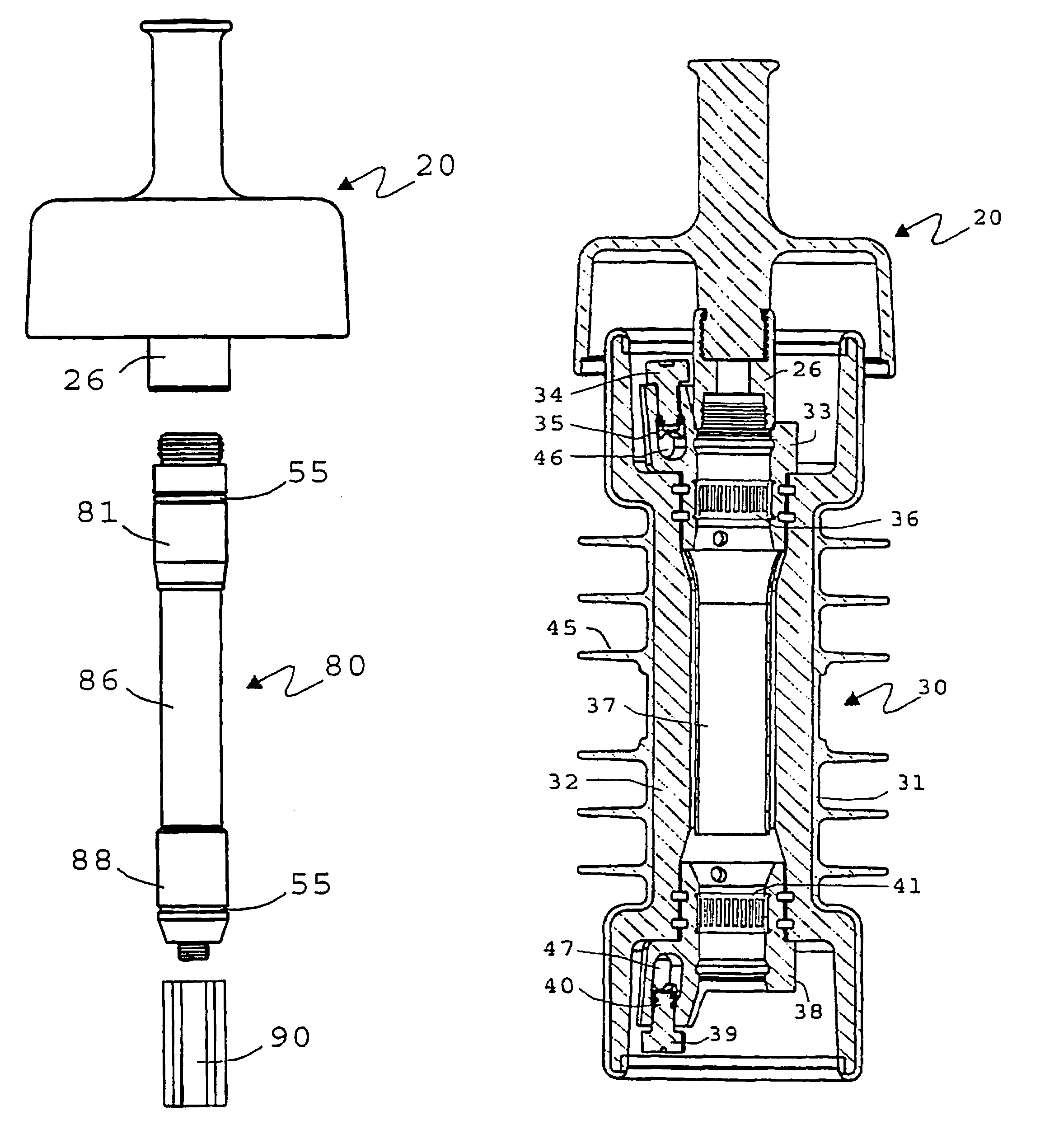
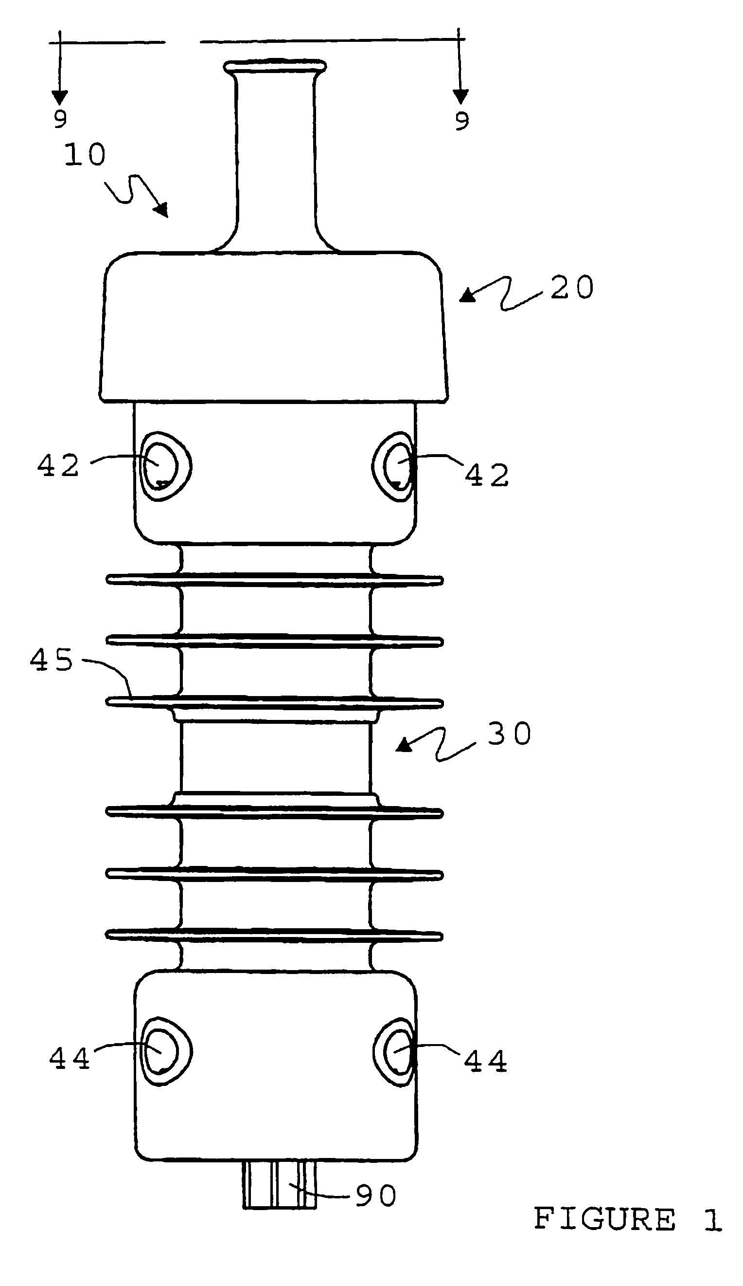
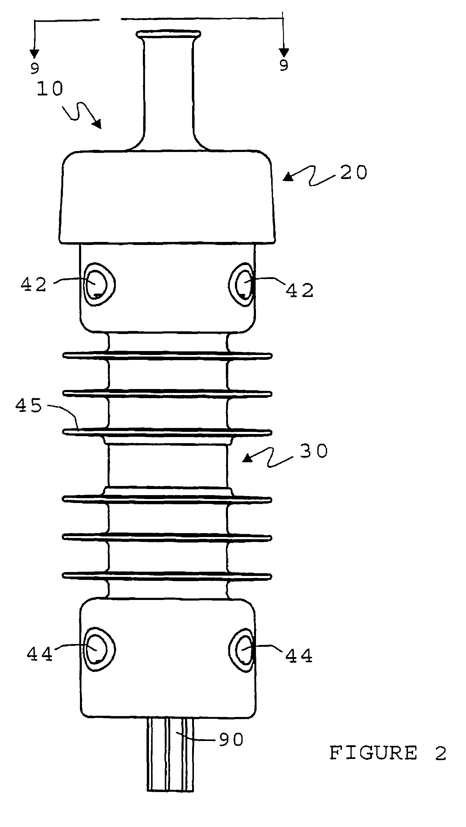
[0040]Referring to FIGS. 1-4, an enclosed insulator assembly 10 is illustrated that can be used as a circuit breaker (FIGS. 1 and 3) or a disconnect switch (FIGS. 2 and 4) by simply installing an interchangeable cutout fuse tube assembly 50 (FIG. 7) or disconnect tube assembly 80 (FIG. 6).

[0041]The enclosed insulator assembly preferably comprises a removable handle 20 and tubular body 30. As best illustrated in FIG. 9, the tubular body 30 and handle 20 comprise an inner tubular thermoplastic core 32 having sufficiently high mechanical strength, good electrical insulation properties and good resistance to heat and chemicals in the context of the intended application. One excellent thermoplastic is offered under the Durethan® trademark. The outer surface of the thermoplastic core of the body and handle is covered with a polymer coating 31, preferably a silicone coating such as polysiloxane. One acceptable material is Dow Coming's SE90166UL material. The resulting body 30 and handle 20...


PUM


Abstract

An enclosed insulator assembly has a generally cylindrical polysiloxane body, a tubular Durethan® core with upper and lower terminals, Multilam™ contacts within the terminals, an arc-quenching tube, and a manually removable handle. Entrance holes in the body accommodate the coupling of external cables to the terminals. A threaded cylinder positioned on the handle's interior accommodates one of an interchangeable cutout fuse tube assembly and disconnect tube assembly and permits the assembly to be inserted into the core as the handle is positioned on the body. Both assemblies have top and bottom fittings with O-rings that prevent weather corrosion between the fittings and terminals. A grooved load interrupter is attached to the bottom fitting of the assemblies to suppress arcing when the assembly is pulled out from the body.

Description

BACKGROUND OF THE INVENTION[0001]The present invention relates to an improved enclosed insulator assembly of the type that functions as an electrical cutout fuse and / or as a disconnect switch and, more particularly, to a connect / disconnect switch for overhead and underground circuits in high voltage distribution systems.BACKGROUND OF THE INVENTION[0002]Electric utility companies have primary and secondary lines for distributing electric power. Primary lines are used to deliver electric power to customer service transformers, which provide electricity to designated geographic areas. Utilities protect these primary lines from overload with circuit breakers or other types of electric current interrupters which trip “off” when a fault condition occurs. (For the sake of brevity, all types of circuit interrupters will hereinafter be referred to as “circuit breakers”; however, it will be known and understood that the use of the term “circuit breaker” includes circuit breakers, cutouts and ...

Claims


Application Information

Patent Timeline
Patent Type & Authority Patents(United States)
IPC IPC(8): H01H71/20H01H85/042
CPCH01H31/127H01B17/005
Inventor HELLER, CARL
Owner IMPACT POWER LLC A DELAWARE LLC
Why Eureka
Try Eureka