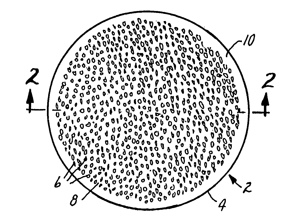
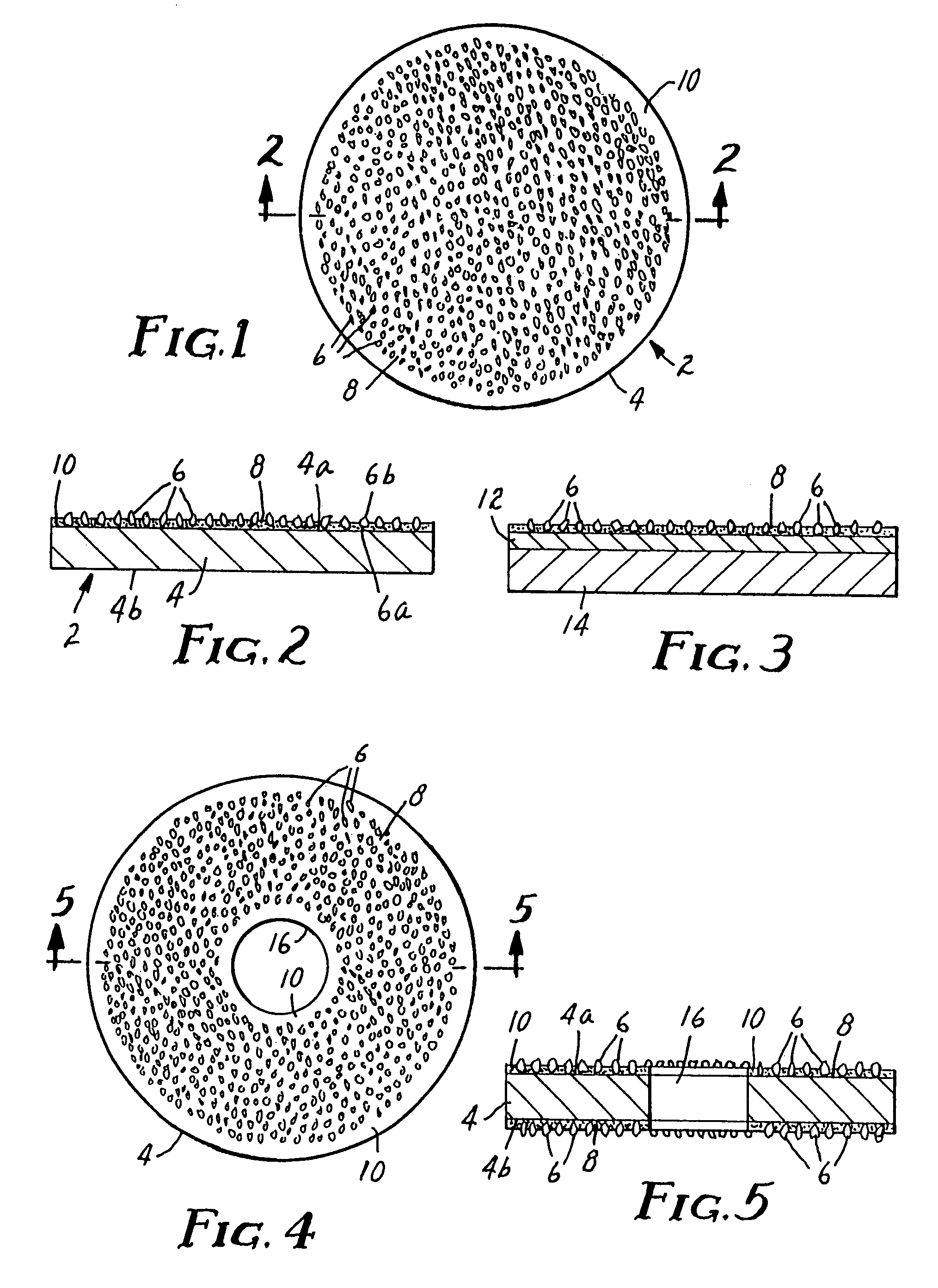
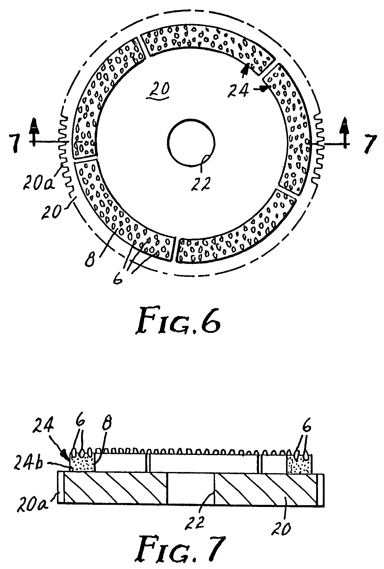
Conditioning disk

a technology of condition disk and abrasive material, which is applied in the field of abrasive articles, can solve the problems of reducing the support for adjacent particles, abrasive particles will have a tendency to be dislodged from the matrix material, and abrasive particles can easily scratch and damage the polished surface of the workpiece, so as to reduce the likelihood of abrasive particles breaking loos

Inactive Publication Date: 2010-01-05
3M INNOVATIVE PROPERTIES CO
View PDF41 Cites 33 Cited by
  • Summary
  • Abstract
  • Description
  • Claims
  • Application Information

AI Technical Summary

Benefits of technology

[0009]A quantity of corrosion resistant powder is admixed with the brazing alloy to improve the bonding properties, enhance the strength, improve the corrosion resistant properties, and reduce the cost of the matrix material. The corrosion resistant powder may include metals and metal alloys including stainless steel, titanium, titanium alloys, zirconium, zirconium alloys, nickel, and nickel alloys. More specifically, the nickel alloy can include nichrome, a nickel alloy including 80% nickel and 20% chrome by weight. Alternatively, the corrosion resistant powder can be formed of ceramics including carbides, such as silicon or tungsten carbide.
[0012]To reduce the likelihood of abrasive particles breaking loose from the substrate in the region where the substrate is cut to the desired shape, the portion of the substrate which is cut may be provided free of abrasive particles. This particle free zone may, for example, extend a certain distance along the entire edge of the substrate. For a typical conditioning disk having a generally circular or annular shape, the particle free zone is provided at the outer peripheral edge portion of the substrate. Depending on the application, abrasive particles can be provided on one or both sides of the substrate.
[0013]The present invention further provides a method of fabricating an abrasive article in which the abrasive particles are affixed to a substrate with a corrosion resistant matrix material including a brazing alloy and a corrosion resistant powder. The method includes first applying a layer of matrix material to the substrate and then arranging the abrasive particles in the matrix material so that a portion of each abrasive particle is surrounded by matrix material. The abrasive particles are arranged on the substrate to provide a particle free zone, thereby eliminating the problem of having abrasive particles in that zone becoming loose as a result of weakness caused by the cutting process. Next, the matrix material is treated with heat and / or pressure to cause the brazing alloy to become liquid and flow between the abrasive particles and between the interstices of the corrosion resistant powder. During this step the brazing alloy forms a chemical bond with the abrasive particles, and forms an inter-metallic compound at the interface with the corrosion resistant powder, thereby bonding the brazing alloy with the corrosion resistant powder. In addition, the combination of heat and pressure causes the corrosion resistant powder to sinter.

Problems solved by technology

Thus, if the abrasive particles are not adequately secured to the substrate, the particles will have a tendency to become dislodged from the matrix material.
Once dislodged, an abrasive particle can easily scratch and damage the polished surface of the workpiece.
In addition, once one particle is dislodged, support for adjacent particles is decreased, and additional particles are more likely to become dislodged.
Electroplating is limited in that not all abrasive particles form adequate bonds with electro-deposited metal.
In addition, not all metals are capable of electrodeposition, therefore limiting the range of metallic compositions which can be used in the electroplating process.
While sintering generally serves to affix the abrasive particles to the substrate, the abrasive particles have a tendency to become dislodged from the matrix material during operation, particularly in a corrosive environment.

Method used


Image

  • Conditioning disk
  • Conditioning disk
  • Conditioning disk

Examples


example

[0033]In a specific embodiment of the invention, 80 / 100 diamond abrasive particles were embedded in a matrix material comprising 20% by weight brazing alloy and 80% by weight stainless steel powder. The brazing alloy used was AMDRY alloy No. 767, available from Sulzer Metco, Westbury, N.Y., which includes nickel, phosphorous, and chromium. The chromium serves to react with and form a chemical bond with the diamond abrasive particles. The stainless steel powder used was Ancor 434L-100, available from Hoeganaes Co., Riverton, N.J. The diamond abrasive particles, brazing alloy, and stainless steel powder were then heated to a temperature in the range of generally between 900 and 1100 degrees Celsius, pressurized to a pressure in the range of generally between 75 and 400 kg / cm2, and maintained at these conditions for a time period of generally between 3 and 15 minutes to allow one or more of the following to occur: (1) the stainless steel to become sintered; (2) the brazing alloy to flo...


PUM

PropertyMeasurementUnit
sizeaaaaaaaaaa
sizeaaaaaaaaaa
sizeaaaaaaaaaa

Abstract

An abrasive article includes a plurality of abrasive particles securely affixed to a substrate with a corrosion resistant matrix material. The matrix material includes a sintered corrosion resistant powder and a brazing alloy. The brazing alloy includes an element which reacts with and forms a chemical bond with the abrasive particles, thereby securely holding the abrasive particles in place. A method of forming the abrasive article includes arranging the abrasive particles in the matrix material, and applying sufficient heat and pressure to the mixture of abrasive particles and matrix material to cause the corrosion resistant powder to sinter, the brazing alloy to flow around, react with, and form chemical bonds with the abrasive particles, and allow the brazing alloy to flow through the interstices of the sintered corrosion resistant powder and form an inter-metallic compound therewith.

Description

[0001]This application is a continuation of U.S. Ser. No. 10 / 641,477, filed Aug. 15, 2003, Issued as U.S. Pat. No. 7,198,553 B2 which is a divisional of U.S. Ser. No. 09 / 664,886, filed Sep. 19, 2000, issued as U.S. Pat. No. 6,629,884 B1, which is a continuation of U.S. Ser. No. 09 / 060,634, filed Apr. 15, 1998, issued as U.S. Pat. No. 6,123,612. the disclosures of which are incorporated by reference in their entirety herein.FIELD OF THE INVENTION[0002]The present invention relates generally to abrasive articles. More particularly, the present invention relates to an abrasive article wherein the abrasive particles are affixed to a substrate with a corrosion resistant matrix material including a sintered corrosion resistant powder and a brazing alloy chemically bonded with the abrasive particles, thereby securely holding the particles in place, and further relates to a method of making such an abrasive article.BACKGROUND OF THE INVENTION[0003]Abrasive articles, such as polishing or con...

Claims


Application Information

Patent Timeline
Patent Type & Authority Patents(United States)
IPC IPC(8): B24B7/00B24B53/017B24B53/12B24D3/00B24D3/08B24D3/34B24D18/00C22C26/00
CPCB24B53/017B24B53/12B24D3/08C22C26/00B24D18/00B24D18/0018B24D3/342
Inventor GOERS, BRIAN D.
Owner 3M INNOVATIVE PROPERTIES CO
Why Eureka
Try Eureka