Induction machine

a technology of rotating machine and coil end, which is applied in the direction of dynamo-electric machines, synchronous motors, magnetic circuit shapes/forms/construction, etc., can solve the problems of pulsation, worse power factor, and loss of one of the advantages of small coil end incidental to concentrated winding, etc., and achieves high productivity and efficient operation.

Inactive Publication Date: 2010-01-05
MITSUBISHI ELECTRIC CORP
View PDF14 Cites 10 Cited by
  • Summary
  • Abstract
  • Description
  • Claims
  • Application Information

AI Technical Summary

Benefits of technology

[0007]The present invention was made to solve the above-described problems of the prior art, and has an object of providing an electric rotating machine in which higher harmonics of magnetomotive force in low order close to fundamental wave are eliminated while keeping high productivity, being an advantage of the concentrated winding type, thus enabling the efficient operation.
[0009]According to the electric rotating machine of the invention, three-phase concentrated winding, in which a ratio between the number of poles and the number of slots of the stator is 1:3, is employed. As a result, there is no higher harmonics of magnetomotive force in low order close to fundamental wave, and thus it is possible to operate an electric rotating machine efficiently. Furthermore, a stator of concentrated winding type enables to provide an electric rotating machine of high productivity of small coil end, high mass production, and high space factor.

Problems solved by technology

This fact results in disadvantages such as occurrence of pulsation (ripple) or worse power factor, in an induction motor of such a type as carrying a current on the secondary side by a magnetic flux that the stator generates and producing a magnetic flux.
Thus, one of the advantages of small coil end incidental to the concentrated winding is lost.
This problem remarkably comes out particularly in motors of a small stack thickness.

Method used


Image

  • Induction machine
  • Induction machine
  • Induction machine

Examples


embodiment 1

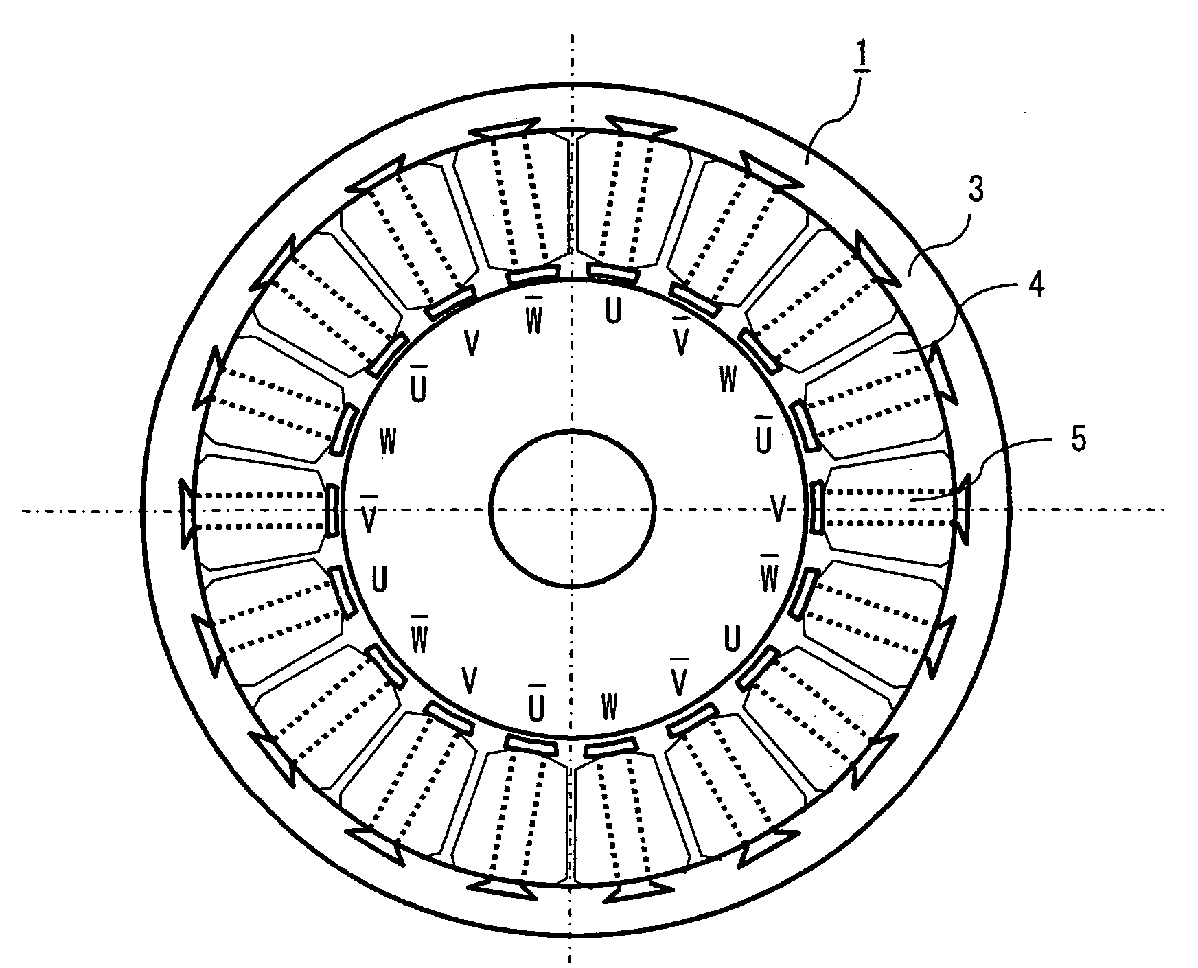
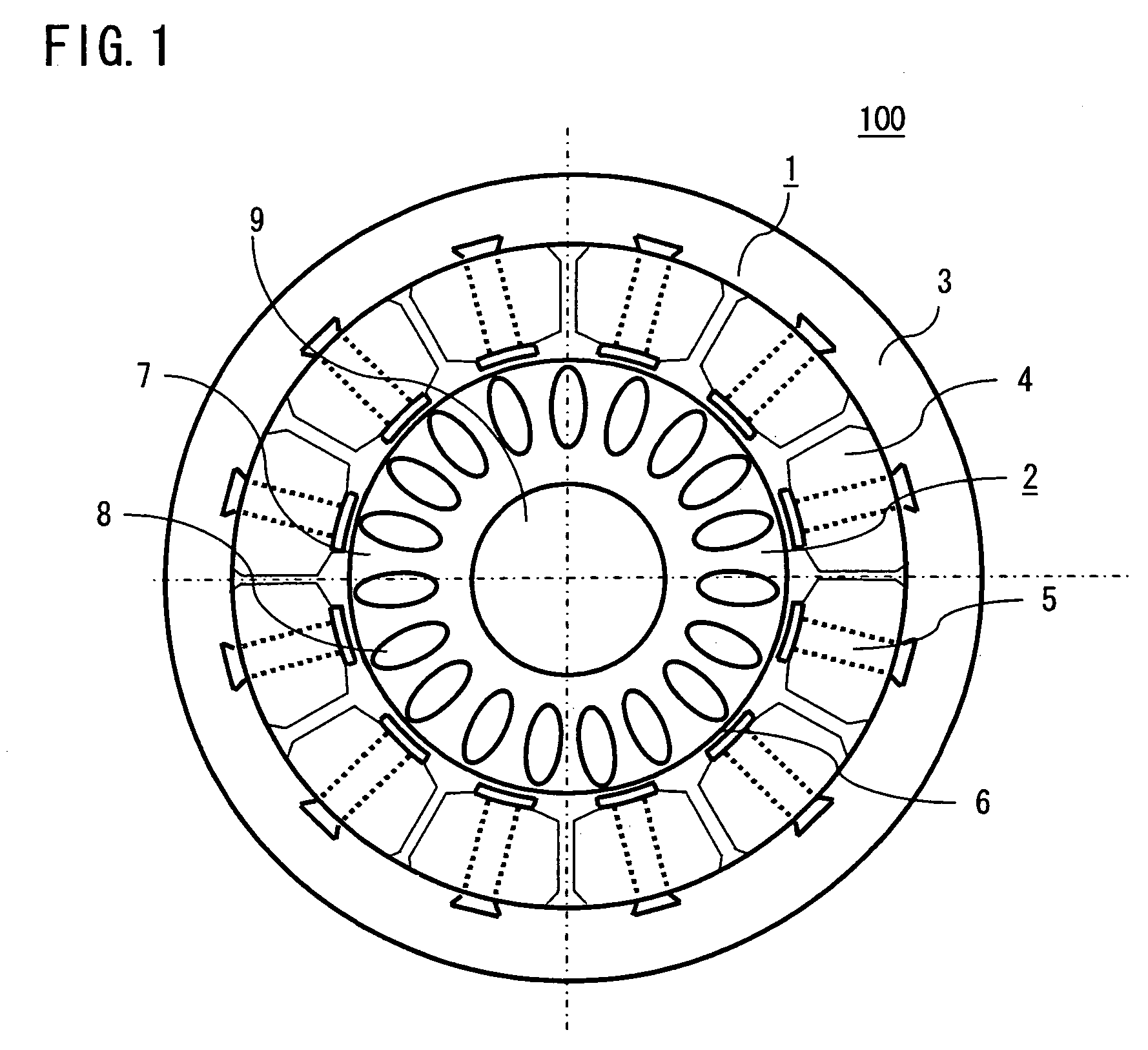
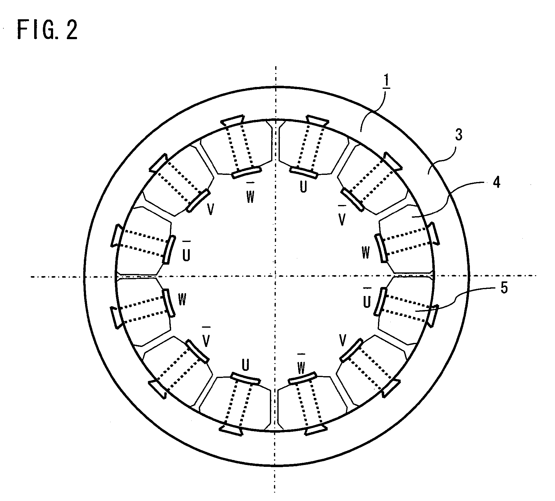
[0023]FIG. 1 is a cross sectional view showing an electric rotating machine, particularly a three-phase concentrated winding induction motor according to a first embodiment of the invention. With reference to FIG. 1, a three-phase concentrated winding induction motor 100 is formed of a stator 1 and a rotor 2. The stator 1 is manufactured by integrally forming a core back 3 that is made by laminating, e.g., an electromagnetic steel plate, and portions in each of which a tooth 5 that is likewise made by laminating, e.g., an electromagnetic steel plate is wound with a coil 4 in a concentrated manner. As shown in FIG. 2, the coils 4 that are wound on each of the teeth 5 are connected to three-phase power supply (U-phase, V-phase, W-phase) respectively, and wound so as to produce a rotating magnetic field to be connected.

[0024]The rotor 2 includes a rotor core 7 that is made by laminating, e.g., an electromagnetic steel plate, and a secondary conductor 8 that is formed by, e.g., aluminum...

embodiment 2

[0037]A resistance R1 of a distributed winding induction machine can be calculated with the following expression (3) letting a length of a coil (copper wire) L and a sectional area of the coil Ac:

[0038]R1=ρ⁢LAC(3)

[0039]Letting a coil length per turn L1, the above L is obtained with the following expression (4) using the number of turns n and the number of slots Ns in each phase:

L=L1nNs  (4)

[0040]Letting an external diameter of the stator Φd, a coil diameter 0.8Φd and the number of poles p, a coil length LE of one coil end portion of the distributed winding induction machine can be calculated with the following expression (5):

[0041]LE=0.8⁢π⁢ϕdp×π2(5)

[0042]Letting an entire slot area As, and a space factor σ, a relation represented by the following expression (6) is established:

[0043]AC=AS⁢σNS⁢n(6)

[0044]As a result, letting core length of the stator LC, the resistance R1 is obtained with the following expression (7):

[0045]R1=ρ×2⁢⁢(LC+LE)⁢⁢nNS×NS⁢nAS⁢σ=2⁢ρ⁢n2⁢NS2AS⁢σ⁢(LC+0.4⁢π2p⁢ϕd)(7)...

embodiment 3

[0072]As described in the foregoing first embodiment, in the concentrated winding induction motor including a concentrated winding stator having a base unit of 3 slots at 1 pole can be efficiently operated since there is no higher harmonics of magnetomotive force in the secondary or 4th order, being different from a concentrated winding stator having a base unit of 3 slots at 2 poles widely used in permanent magnet-type motors.

[0073]It is to be noted that, in case of large higher harmonics of magnetomotive force in the 5th or 7th order, the pulsation (ripple) of torque is often increased. To cope with this, according to this second embodiment, the more efficient operation of a concentrated winding induction motor is achieved by decreasing higher harmonics of magnetomotive force in the 5th order.

[0074]Higher harmonics of magnetomotive force in the 5th order has awavelength of ⅕ that of fundamental wave. To be less affected by this 5th higher harmonics of magnetomotive force, a second...


PUM


Abstract

An electric rotating machine comprises: a stator in which a coil is wound on a plurality of teeth in concentrated winding, and the coil is connected to a three-phase power supply; and a rotor disposed in opposition to the teeth of the stator; wherein a ratio between the number of poles and the number of slots of the stator is 1:3. There is no higher harmonics of magnetomotive force in low order close to fundamental wave, thus enabling efficient operation of the electric rotating machine. Furthermore, owing to the stator of concentrated winding, it is possible to provide an electric rotating machine of high productivity with small coil end, high mass production, and high space factor.

Description

BACKGROUND OF THE INVENTION[0001]1. Field of the Invention[0002]The present invention relates to an electric rotating machine and, more particularly, to an electric rotating machine including a stator to which concentrated winding is applied.[0003]2. Description of the Related Art[0004]Conventionally, in stators of a three-phase induction motor, distributed winding has been applied. On the other hand, in permanent magnet-type motors, stators to which concentrated winding is applied are often employed. A large difference between a concentrated winding stator and a distributed winding stator is that in the concentrated winding stator, there is a negative-phase magnetic flux (running in a direction opposite to a rotational direction) in frequency close to fundamental wave in a magnetomotive force waveform. This fact results in disadvantages such as occurrence of pulsation (ripple) or worse power factor, in an induction motor of such a type as carrying a current on the secondary side by...

Claims


Application Information

Patent Timeline
Patent Type & Authority Patents(United States)
IPC IPC(8): H02K17/00
CPCH02K17/16H02K2201/06
Inventor NAKAYAMA, MISANAKA, KOUKIMORITA, MASAOINOUE, MASAYASHIMADA, AKIHIRO
Owner MITSUBISHI ELECTRIC CORP
Why Eureka
Try Eureka