Light diffusing sheet and backlight unit using the light diffusing sheet

a technology backlight unit, which is applied in the direction of lighting and heating apparatus, instruments, synthetic resin layered products, etc., can solve the problems of poor productivity, increased cost, and difficult continuous production of light diffusing film, so as to achieve continuous and efficient production, easy formation, and easy production

Inactive Publication Date: 2010-01-12
TAKIRON CO LTD
View PDF21 Cites 25 Cited by
  • Summary
  • Abstract
  • Description
  • Claims
  • Application Information

AI Technical Summary

Benefits of technology

[0014]A light diffusing sheet in which fine recesses having a shape which is any of the shape of an inverted polyangular pyramid, the shape of an inverted truncated polyangular pyramid, the shape of an inverted cone, and the shape of an inverted truncated cone have been formed in at least one of the surfaces thereof as in the first light diffusing sheet of the invention is free from the trouble that the surface having fine recesses mars a film, etc., because in this light diffusing sheet, the vertex parts of the recesses in the surface are connected in all directions and are flat. These fine recesses can be easily formed by embossing. This light diffusing sheet can hence be continuously and efficiently produced by subjecting a sheet formed by melt extrusion to embossing with an embossing roll or the like. In particular, in the case of forming recesses regularly arranged, embossing with a roll is easy and these recesses can be easily formed. Consequently, the first light diffusing sheet of the invention is less apt to mar a lens film, etc., and attains high productivity and a cost reduction as compared with the light diffusing film (sheet) disclosed in patent document 1, which is produced one by one by injection molding or the like. In addition, the light diffusing sheet can be easily produced in a small thickness.
[0015]When the first light diffusing sheet of the invention is disposed so that the surface thereof which has fine recesses formed therein serves as a light emission side, then the light which has entered after having passed through the lightguide plate or having been emitted by the light source is converted to diffused light having a small brightness peak angle due to the light-refracting function of the inclined faces of the fine recesses having the shape of an inverted polyangular pyramid or inverted truncated polyangular pyramid or the light-refracting function of the tapered surfaces of the fine recesses having the shape of an inverted cone or inverted truncated cone, before being emitted and led to the lens film. Consequently, by bringing this diffused light having a small brightness peak angle to the front direction (the direction perpendicular to the screen of the liquid-crystal display) by the lens film, the luminance of the screen of the liquid-crystal display can be sufficiently heightened. In addition, since light is intensely diffused by the fine recesses, the dots on the lightguide plate and the bright lines attributable to the light source become less apt to be visually recognized. Namely, hiding properties are improved and the generation of a moiré or interference fringe is inhibited. In this case, when the light diffusing sheet contains a light diffusing agent, light is diffused more intensely to increase the haze. Because of this, the hiding properties are improved further and the effect of inhibiting the generation of a moiré or interference fringe is also improved.
[0016]The function of reducing the brightness peak angle of the diffused light emitted from the light diffusing sheet is remarkable when the bevel between the surface having fine recesses formed (light emission side) and each inclined face of each fine recess having the shape of an inverted polyangular pyramid or inverted truncated polyangular pyramid or the bevel between that surface and the ridgeline of each fine recess having the shape of an inverted cone or inverted truncated cone is 15-70° and when the proportion of the area occupied by the fine recesses in the surface having the fine recesses formed therein (light emission side) is 30-100%. Furthermore, when that bevel in the fine recesses is 35-70° and the areal proportion of the fine recesses is 30-100%, then the light which remained unemitted due to the total reflection of part of incident light and has been returned by a light reflection sheet or the like and entered the light diffusing film again can be efficiently emitted. Because of this, luminance can be improved without reducing haze.
[0017]Furthermore, the light diffusing sheet in which the fine recesses have been formed in an oblique-line arrangement is effective in making a moiré or interference fringe less visible and does not cause luminance unevenness.
[0009]The second light diffusing sheet of the invention comprises a core layer made of a light-transmitting resin and a surface layer laminated to at least one of the surfaces of the core layer and made of a light-transmitting resin or of a light-transmitting resin containing a light diffusing agent, and is characterized in that the surface layer has, formed in the surface thereof, fine recesses having a shape which is any of the shape of an inverted polyangular pyramid, the shape of an inverted truncated polyangular pyramid, the shape of an inverted cone, and the shape of an inverted truncated cone.
[0019]In the case where the surface layers of the second light diffusing sheet are made of alight-transmitting resin containing no light diffusing agent, the following effect is brought about. Even when the core layer of this sheet contains a light diffusing agent, formation of this sheet by melt extrusion molding (three-layer coextrusion molding) does not result in the so-called eye mucus phenomenon in which the light diffusing agent adheres to the periphery of the extrusion orifice, because the core layer is covered by the light-transmitting resin constituting the surface layers. Consequently, the sheet surfaces can be prevented from bearing streak lines. On the other hand, in the case where the surface layers contain a light diffusing agent, not only light diffusing properties are improved, but also the surface layers can have a reduced coefficient of linear expansion. Consequently, this light diffusing sheet can be prevented from rumpling, especially after the sheet is incorporated in a backlight unit and illuminated.
[0020]In the first and second light diffusing sheet of the invention in which the surface thereof on the side opposite to the surface having fine recesses formed has recesses and protrusions which are finer than the fine recesses, light diffusion is further enhanced by these microfine recesses and protrusions and this further improves hiding properties. Furthermore, those in which a functional layer having light-transmitting properties, such as an ultraviolet-absorbing layer or an antistatic layer, has been laminated to the surface on the side opposite to the surface having fine recesses formed have an advantage that the function of the functional layer, such as, e.g., the prevention of deterioration by ultraviolet or the prevention of dust particle adhesion, is exhibited.
[0021]In the first backlight unit of the invention, the light which has passed through the lightguide plate and entered the light diffusing sheet of the invention having a thickness of 50-300 μm and which has a large brightness peak angle is brought to a direction where the brightness peak angle becomes small by the emission-side fine recesses having a shape which is any of the shape of an inverted polyangular pyramid, the shape of an inverted truncated polyangular pyramid, the shape of an inverted cone, and the shape of an inverted truncated cone. As a result, the light is emitted as diffused light having a small brightness peak angle. When a lens film has been disposed in front, the diffused light having a small brightness peak angle is led to the lens film and brought to the front direction by the lens film.
[0022]In the second backlight unit of the invention, the light which has been emitted by the light source and entered the light diffusing sheet of the invention having a thickness of 0.3-5 mm and which has a large brightness peak angle is likewise emitted after having been converted to diffused light having a small brightness peak angle by the emission-side fine recesses. When a lens film has been disposed in front, the diffused light is led to the lens film and brought to the front direction by the lens film.
[0023]Consequently, by incorporating these backlight units so as to be disposed on the back side of, e.g., the screen of a liquid-crystal display, not only the luminance of the display screen is sufficiently heightened but also the dots on the back side of the lightguide plate and bright lines attributable to the light source are prevented from being visually recognized.

Problems solved by technology

However, this light diffusing film (sheet) having projections of a rectangular pyramid shape is difficult to continuously produce by forming a film by melt extrusion and embossing the film with an embossing roll or the like.
There have hence been problems that the light diffusing film has poor productivity and an increased cost and that it is not easy to produce thin films having a thickness of 150 μm or smaller.
In addition, the formation of projections of a rectangular pyramid shape regularly arranged lengthwise / crosswise as in this light diffusing film (sheet) has had problems that marring is apt to occur because of the projections and this is causative of defects and that the projections may cause a moiré or interference fringe, resulting in luminance unevenness.

Method used


Image

  • Light diffusing sheet and backlight unit using the light diffusing sheet
  • Light diffusing sheet and backlight unit using the light diffusing sheet
  • Light diffusing sheet and backlight unit using the light diffusing sheet

Examples


example 1

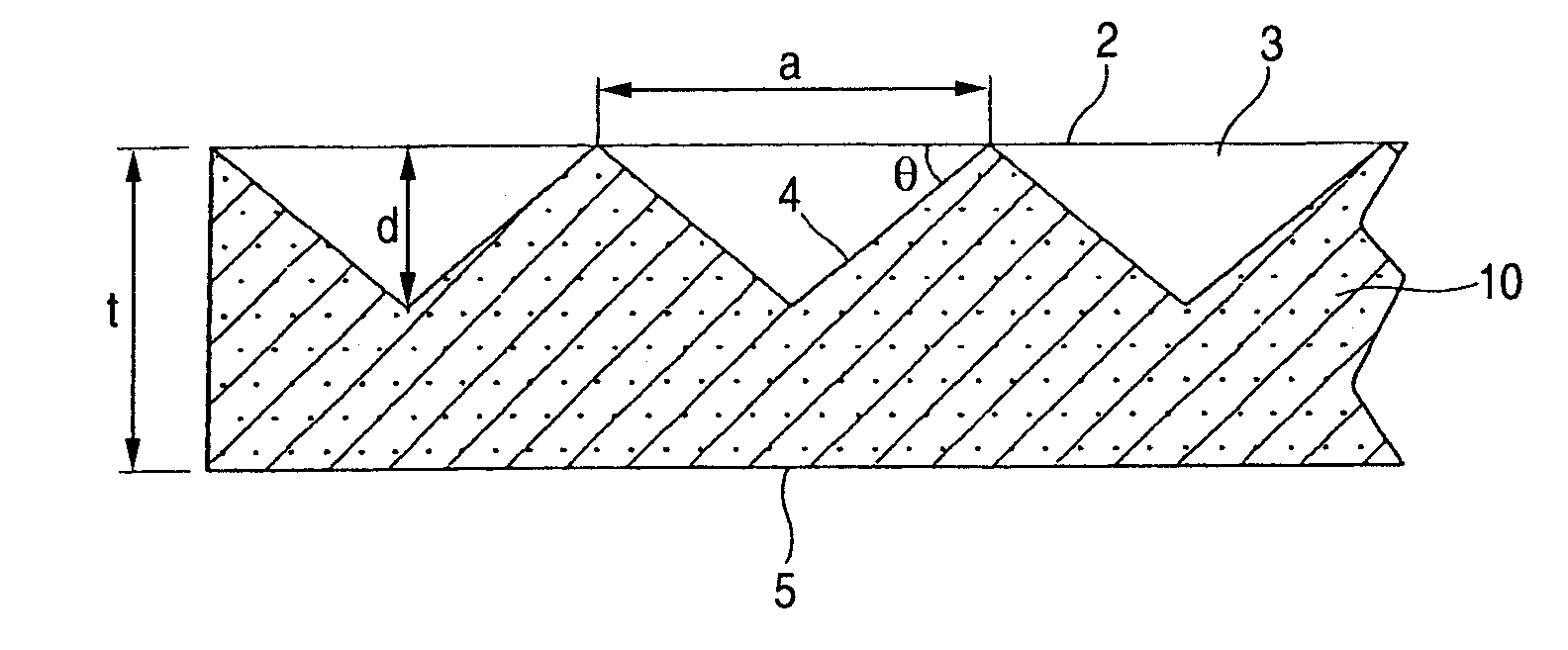
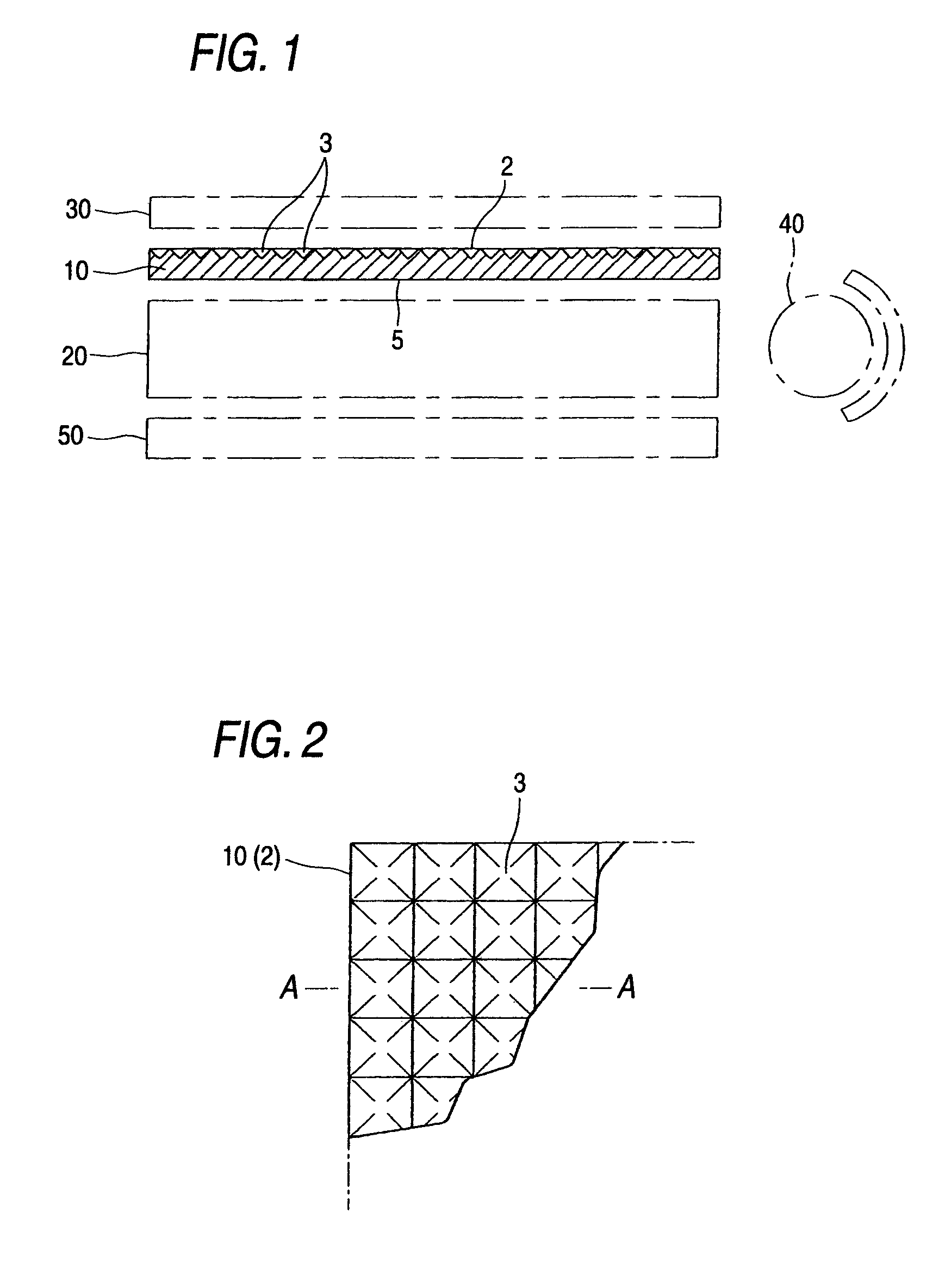
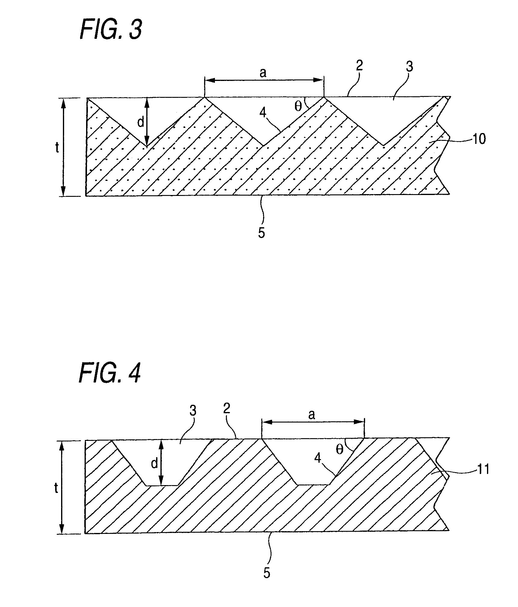
[0052]FIG. 1 is a diagrammatic sectional view of a light diffusing sheet according to one embodiment of the invention, and shows the light diffusing sheet incorporated in a backlight unit of the edge light type indicated by the imaginary lines. FIG. 2 and FIG. 3 are an enlarged plan view and an enlarged sectional view each illustrating part of the light diffusing sheet.

[0053]This light diffusing sheet 10 comprises a light-transmitting resin sheet which contains a light diffusing agent and in which fine recesses 3 having the shape of an inverted regular quadrangular pyramid have been formed in order in one upper surface 2 serving as a light emission side. As shown in FIG. 1, this light diffusing sheet 10 is intended to be incorporated into a backlight unit of the edge light type so that the light diffusing sheet 10 is disposed between a lightguide plate 20 and a lens film (prism film) 30 disposed over (in front of) the lightguide plate 20. In FIG. 1, numeral 40 denotes a light source...

example 2

[0080]FIG. 4 is an enlarged sectional view illustrating part of a light diffusing sheet according to another embodiment of the invention. This light diffusing sheet 11 comprises a light-transmitting resin sheet which contains no light diffusing agent and in which fine recesses 3 having the shape of an inverted truncated regular quadrangular pyramid have been formed apart from one another in a lengthwise / crosswise arrangement in the upper surface 2 serving as a light emission side.

[0081]The light-transmitting resin to be used in this embodiment can be any of the aforementioned light-transmitting resins having a high total light transmittance. However, it is especially preferred to select a resin which has high heat resistance even when no light diffusing agent is contained therein and which is free from troubles such as rumpling after incorporation in a backlight unit. Examples of such resins include polycarbonates, polyesters (in particular, biaxially stretched poly(ethylene terepht...

example 3

[0085]FIG. 5 is an enlarged sectional view illustrating part of a light diffusing sheet according to still another embodiment of the invention. This light diffusing sheet 12 comprises a core layer 1 (light diffusing sheet main body) made of a light-transmitting resin containing a light diffusing agent and surface layers 6 and 6 which are made of a light-transmitting resin and have been laminated respectively to both sides of the core layer 1. The upper surface layer 6 serving as a light emission side has fine recesses 3 having the shape of an inverted regular quadrangular pyramid described above continuously formed in a lengthwise / crosswise arrangement in the surface 2 of the layer 6. The lower surface layer 6 serving as a light entrance side has surface recesses and protrusions 7 which are finer than the fine recesses 3 and have the arithmetic mean deviation of the profile of 10 μm or lower.

[0086]Although the core layer 1 in this embodiment contains a light diffusing agent, the lay...


PUM

PropertyMeasurementUnit
thicknessaaaaaaaaaa
thicknessaaaaaaaaaa
thicknessaaaaaaaaaa

Abstract

To provide a light diffusing sheet which enables the light from a lightguide plate or light source of a backlight unit to be conducted to lens film after having been converted to diffused light having a small brightness peak angle, and which generates neither a moiré or interference fringe nor luminance unevenness, and is advantageous also in terms of productivity and cost, and to provide a backlight unit having this light diffusing sheet incorporated therein, and the surface of the sheet with fine recesses formed therein serves as a light emission side. The light diffusing sheet comprises a light-transmitting resin, characterized by having fine recesses formed in at least one of the surfaces thereof, the fine recesses having a shape which is any of the shapes of an inverted polyangular pyramid, an inverted truncated polyangular pyramid, an inverted cone, and an inverted truncated cone.

Description

FIELD OF THE INVENTION[0001]The present invention relates to a light diffusing sheet to be incorporated in the backlight unit of a liquid-crystal display for notebook type personal computers, personal computer monitors, television receivers, and the like, or in a screen for advertising signboards, illumination, or image displaying, or in an apparatus such as a scanner or copier. The invention further relates to a backlight unit having the light diffusing sheet incorporated therein.BACKGROUND ART[0002]A backlight unit of the general edge light type for liquid-crystal displays is constituted of a lightguide plate having dots for light diffusion printed on the back side thereof, a light source (e.g., a cold cathode fluorescent tube or LEDs) disposed on one or each side of the lightguide plate, a light diffusing film superposed on the lightguide plate, a lens film (prism film) superposed on the light diffusing sheet, etc.[0003]One role of the light diffusing film in the backlight unit i...

Claims


Application Information

Patent Timeline
Patent Type & Authority Patents(United States)
IPC IPC(8): F21V7/04F21V5/00B32B3/30B32B7/02B32B27/18F21V8/00G02B5/02
CPCB32B3/30B32B27/18G02B5/0221G02B6/0051G02B5/0242G02B5/0278G02B6/0038G02B5/0231G02F1/1335
Inventor KUROKAWA, YUJIOMURA, YUTAKA
Owner TAKIRON CO LTD
Why Eureka
Try Eureka