Triple grating optical encoder and modified triple grating optical encoder for displacement detection

a technology of optical encoder and triple grating, which is applied in the direction of converting sensor output optically, instruments, measurement devices, etc., can solve the problems too large dispersion of signal amplitude of encoder, and decline of signal level, so as to achieve stable performance and reduce the effect of deterioration of reliability and high reliability

Active Publication Date: 2010-01-19
OLYMPUS CORP
View PDF3 Cites 7 Cited by
  • Summary
  • Abstract
  • Description
  • Claims
  • Application Information

AI Technical Summary

Benefits of technology

[0024]The present invention is made in view of the abovementioned circumstances, and the object of the present invention is to provide an encoder which has a stable performance, a high reliability, and a small size, and which is suitable for mass production at low cost.
[0047]in a range of the third effective width W3 of the third grating, the signal strength of the self-image formed on the third grating is reinforced due to the pitches of the self-image and the third grating.
[0049]in a range of the third effective width W3 of the array photodetector, the signal strength of the self-image is reinforced due to the pitch of the self-image and the pitch p3 of the array photodetector.

Problems solved by technology

Because of these defects, size-reduced encoder heads may cease to function as an encoder, and this may lead to a deterioration of reliability.
However, such a structure has caused too large dispersion in the signal amplitude of encoders, particularly, a decline of the signal level.
Consequently, encoders suitable for mass production could not be realized.
On the other hand, from a manufacturing point of view, disposing by mounting a first grating 110 and a third grating 130 such that Δzd is in a range of ±35 μm, involves a high degree of difficulty in the mass production stage.
Moreover, since the dimensional tolerance of structural members become strict in the direction of thickness, the z direction, it is revealed that it is very difficult to propose an optical encoder of this type at a low cost.
When the first grating and the third grating are simply formed on separate members in order to manufacture low-cost optical encoders while securing the reliability, due to the too large dispersion of mounting accuracy of the gratings in a direction of height, it is not possible to achieve encoder signals having an even amplitude, at the time of mass production.

Method used


Image

  • Triple grating optical encoder and modified triple grating optical encoder for displacement detection
  • Triple grating optical encoder and modified triple grating optical encoder for displacement detection
  • Triple grating optical encoder and modified triple grating optical encoder for displacement detection

Examples


first embodiment

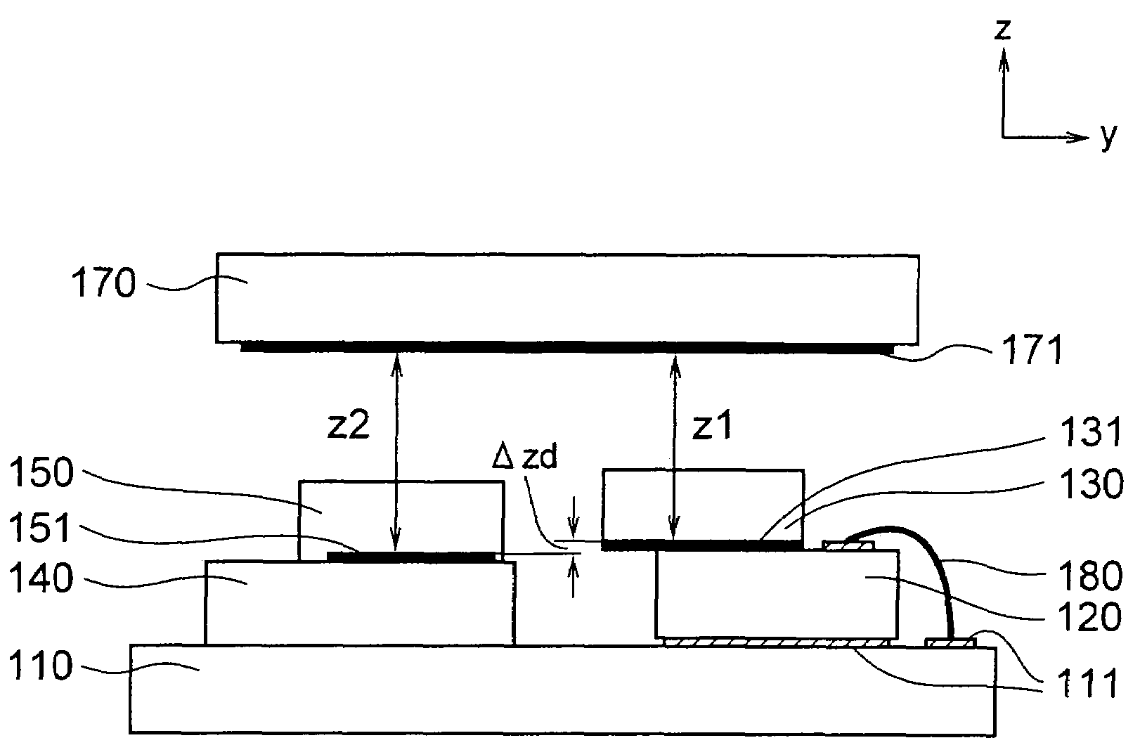
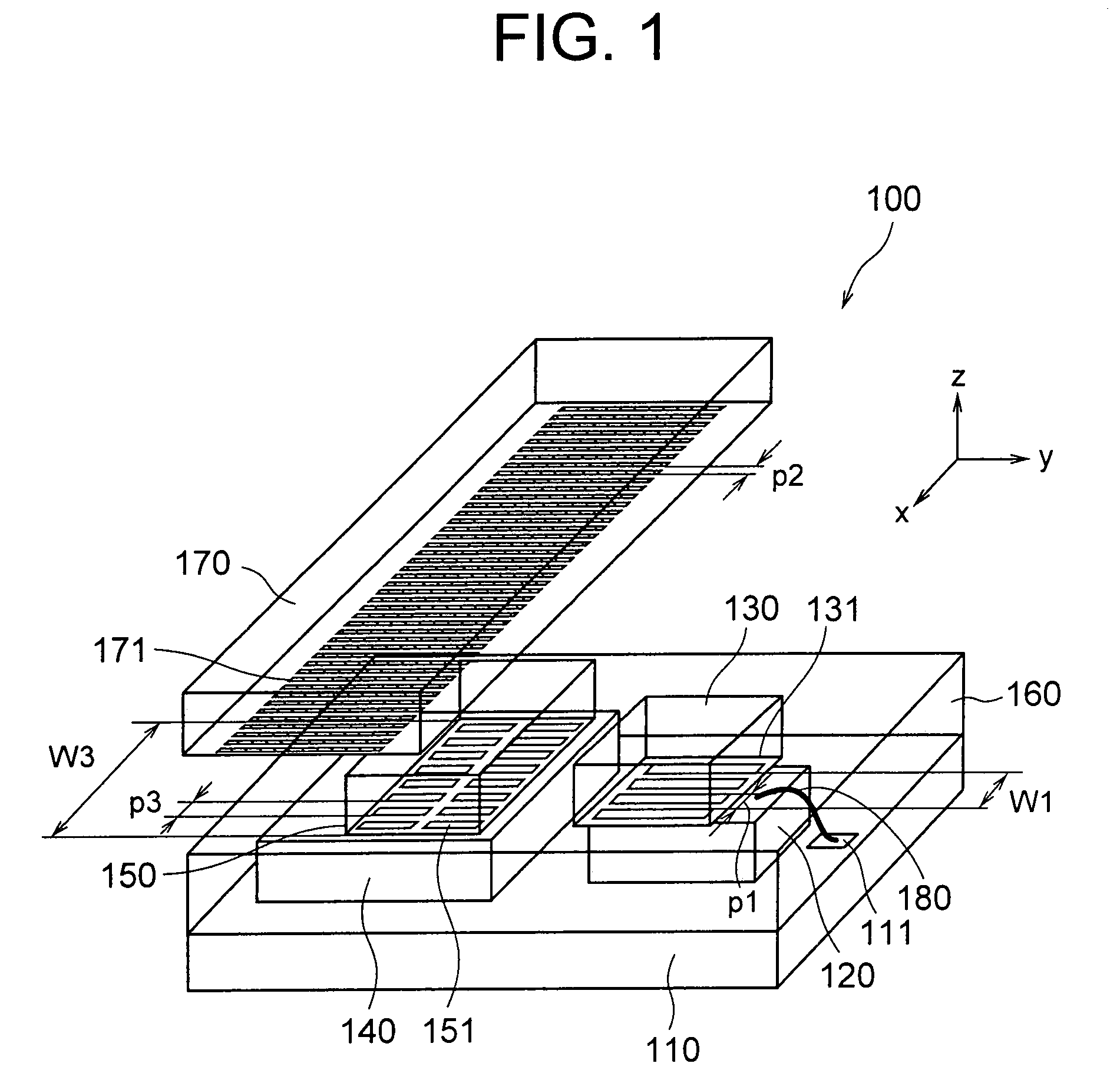
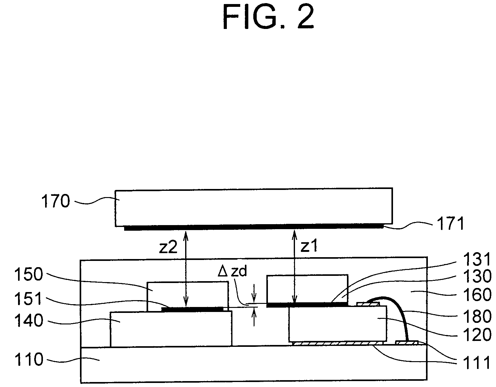
[0141]An optical encoder according to a first embodiment of the present invention is shown in FIG. 1 and FIG. 2. FIG. 1 is a perspective view and FIG. 2 is a cross-sectional view. Moreover, three-axes rectangular coordinate system of x, y, and z axes as shown in the diagram, has been set.

[0142]In FIG. 1, the optical encoder includes mainly seven components namely a substrate 110, a bare LED 120 which is a bare chip, a light transmission substrate 130 having a first grating 131 of a pitch p1, a photodetector 140 having four light receiving sections, a light transmission substrate 150 having a third grating 151 of a pitch p3, a light transmitting resin 160, and a scale 170 having a second grating 171 of a pitch p2.

[0143]The substrate 110, the bare LED 120 disposed on the substrate 110, the light transmission substrate 130 disposed to be protruding in an x direction and a y direction on the bare LED 120, the photodetector 140 disposed on the substrate 110, and the light transmission su...

second embodiment

[0245]Next, a second embodiment of the present invention will be described below by referring to FIG. 4 and FIG. 5. A photodetector, which includes a PD (photodiode) array in which the third grating 151 and the light receiving section are integrated, is included as a component. FIG. 4 is a perspective view and FIG. 5 is a cross-sectional view. Moreover, as shown in the diagram the coordinate system of x y z is set.

[0246]In FIG. 4, an optical encoder includes mainly six components namely the substrate 110, the bare LED 120 which is a bare chip, the light transmission substrate 130 having the first grating 131 of the pitch p1, a photodetector 140 having a photodiode array 141 (hereinafter, called appropriately as ‘PD array’) of the pitch p3, the light transmitting resin 160, and the scale 170 having the second grating 171 of the pitch p2.

[0247]The substrate 110, the bare LED 120 disposed on the substrate 110, the light transmission substrate 130 disposed to be protruding in the x dire...

modified embodiment

[0285]A modified embodiment of the second embodiment of the present invention is shown in FIG. 6. FIG. 6 is a cross-sectional view. As shown in the diagram, the coordinate system of x y z is set.

[0286]This modified embodiment is an embodiment in which the light transmitting resin 160 is excluded from the second embodiment. From the aspect of physical and electrical reliability, portion, only the wiring portion may be protected by resin potting etc. Moreover, the entire head section may be put in a case made of ceramic etc., and may be sealed with a lid.

[0287]In this modified embodiment, similarly as in the first embodiment, p2, z1, z2, n, W1, and W3 are set such that expression 16 to expression 18 are satisfied. However, in this case, the refractive indices n corresponding to resin, are all replaced by n=1. The thickness of each member is to be set such that z1 and z2 which are calculated by applying expression 14 and expression 15 to the embodiment of the present invention become a...


PUM


Abstract

In a triple slit optical encoder, a first grating and a third grating are formed on separate members, and values of a first effective width W1 and a first pitch p1 of an optical pattern on the first grating, and a third effective width W3 and a third pitch p3 of an optical pattern on the third grating are set to values such that a periodic signal having the amplitude effective for detection of a relative displacement of a scale is achieved based on periodicity of the self-image, refractive indices of substances of substances and / or spaces interposed in the optical path from a bare LED up to a photodetector, and the thickness of those substances and / or spaces in a direction substantially perpendicular to a plane on which the second grating is formed.

Description

CROSS-REFERENCE TO RELATED APPLICATION[0001]The present application is based upon and claims the benefit of priority from the prior Japanese Patent Application No. 2006-245339 filed on Sep. 11, 2006; the entire content of which are incorporated herein by reference.BACKGROUND OF THE INVENTION[0002]1. Field of the Invention[0003]The present invention relates to an optical displacement sensor which is used for detection of a displacement of an encoder etc., and particularly, to an optical encoder.[0004]2. Description of the Related Art[0005]A general example of an optical encoder according to a conventional technology is an optical encoder called as a triple slit type optical encoder. This optical encoder includes a light source such as an LED (light emitting diode), a first grating which is disposed in an optical path of light from the light source, a second grating which is disposed on a scale which receives light from the first grating, a third grating on which a light which has pas...

Claims


Application Information

Patent Timeline
Patent Type & Authority Patents(United States)
IPC IPC(8): G01D5/34
CPCG01D5/34746G01D5/38
Inventor HANE, JUNYAMAMOTO, EIJIKURODA, YOSHIMIKOMAZAKI, IWAO
Owner OLYMPUS CORP
Why Eureka
Try Eureka