Ejector system for vehicle

a technology of ejector system and control unit, which is applied in the direction of electrical control, process and machine control, instruments, etc., can solve the problems of increasing flow rate, giving a sense of discomfort to the driver, and difficult controlling the air-fuel ratio accurately, so as to reduce the fluctuation of idle speed, minimize inconvenience, and reduce the effect of pressur

Inactive Publication Date: 2010-01-19
TOYOTA JIDOSHA KK
View PDF26 Cites 19 Cited by
  • Summary
  • Abstract
  • Description
  • Claims
  • Application Information

AI Technical Summary

Benefits of technology

[0015]With the ejector system for a vehicle described above, fluctuations in the intake air flow-rate are suppressed, because the intake air flow-rate is adjusted in accordance with a change in the operating state of the ejector. Accordingly, it is possible to appropriately suppress fluctuations in the idle speed of the internal combustion engine.
[0041]The cross-section of the passage formed within the ejector is gradually decreased toward the portion at which a negative pressure is generated. Accordingly, the intake air flow-rate gradually increases when the ejector is caused to operate. Namely, the intake air flowing through the ejector does not promptly respond to an increase in the intake air flow-rate. Based on this, the intake air flow-rate that is indicated by the control amount which needs to be responsive to a change in the intake air flow-rate, more specifically, the control amount used in the feedback control executed to suppress fluctuations in the idle speed may be adjusted by the idle-speed adjustment device that promptly deals with a change in the intake air flow-rate to appropriately control the idle speed. With the ejector system for a vehicle described above, it is possible to cause the ejector to operate more frequently without affecting the maintenance of the idle speed. Thus, a negative pressure is obtained in advance. Accordingly, it is possible to minimize the inconvenience that is caused when the ejector is caused to operate as needed and that is caused by a delay in response to a change in the intake air flow-rate during the transitional period when a negative pressure is obtained.

Problems solved by technology

However, Japanese Patent Application Publication No. 2005-69175 (JP-A-2005-69175) does not describe the manner in which the intake air flow-rate increases.
When the intake air flow-rate is transiently changing, controlling the air-fuel ratio accurately is likely to be difficult due to the delayed response to the detection of the intake air flow-rate.
In this case, such fluctuations may give a sense of discomfort to the driver.
However, when the intake air flow-rate is transiently changing, the learning is not always properly executed as intended.
Therefore, if the learning is executed even when the ejector is caused to operate, the learning control amount may be considerably small.
In addition, the intake air flow-rate becomes severely deficient.
In some cases, the feedback control fails to be executed in time, and therefore engine stalling may occur.
Accordingly, if a negative pressure having a large absolute value needs to be generated by the ejector, the idle speed inevitably excessively increases due to the structure.
Namely, due to the structure of the negative pressure generator described above, the ejector is not efficiently used when the absolute value of the negative pressure to be introduced from the intake system of the internal combustion engine is large.
Accordingly, it is considered that the ejector is not efficiently used when the absolute value of the negative pressure to be introduced from the internal combustion engine is large.
Accordingly, a required negative pressure may not be obtained in time.

Method used


Image

  • Ejector system for vehicle
  • Ejector system for vehicle
  • Ejector system for vehicle

Examples


first embodiment

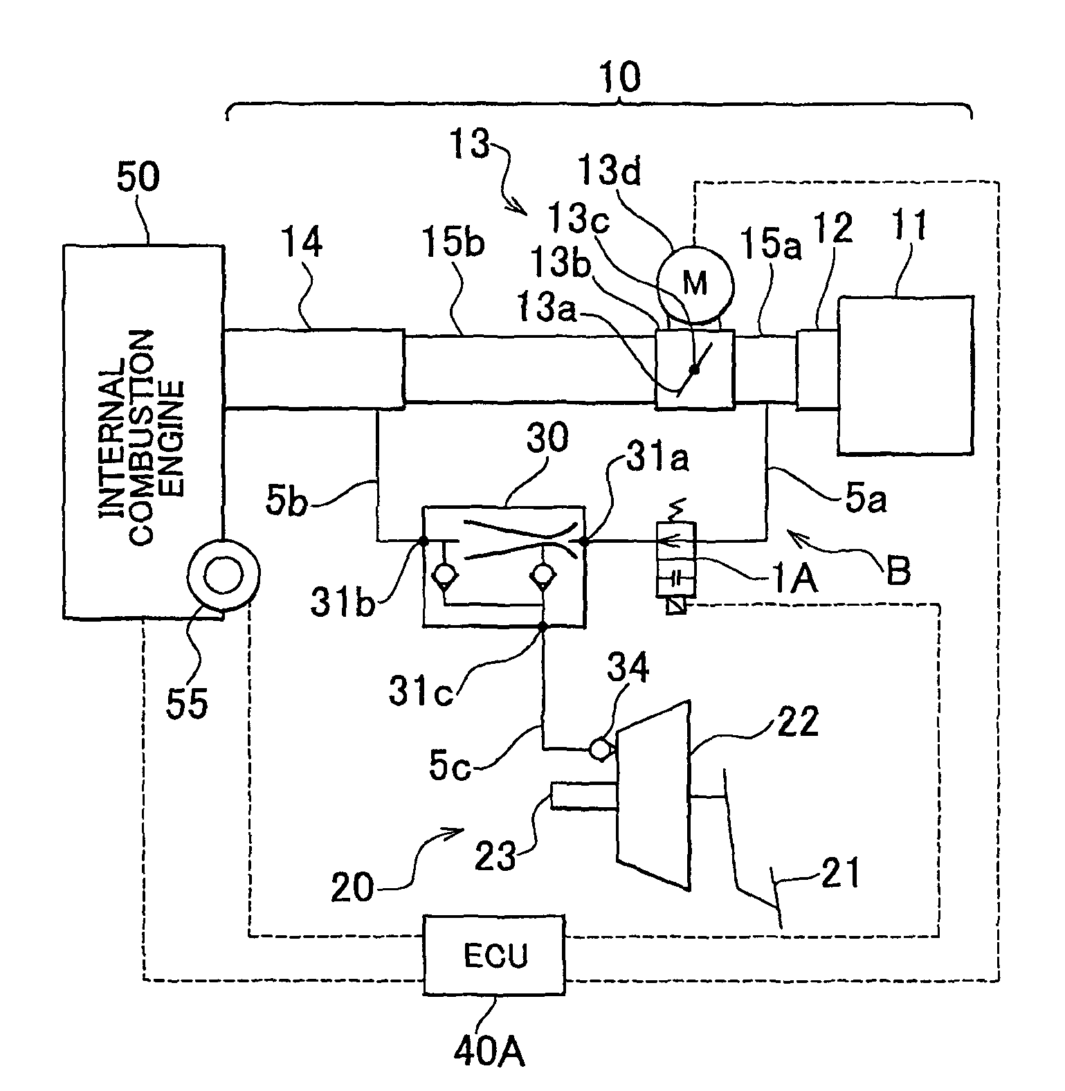
[0070]The ROM stores programs in which various processes executed by the CPU are written. According to the invention, the ROM stores the vacuum switching valve 1A control program used to control the vacuum switching valve 1A to cause the ejector 30 to operate or cause the ejector 30 to stop operating under various conditions, and the idle-speed control program used to control the electric throttle valve system 13 to control the idle speed, etc. in addition to the program used to control the internal combustion engine 50. These programs may be combined with each other. The idle-speed control program includes the feedback control amount changing program, the control amount learning program, the correction control amount increase / decrease program, the idle-speed control amount calculation program, and the electric throttle valve system control program. According to the feedback control amount changing program, the feedback control amount is changed based on the difference between the t...

third embodiment

[0080]At the same time, the gain of the integral term in the equation for calculating the feedback correction amount is increased before the feedback correction amount is calculated. Thus, even if the feedback control amount is changed by a larger amount, the feedback control amount is made substantially equal to the target feedback control amount promptly. If this process is not executed, it is difficult to make the feedback control amount substantially equal to the target feedback control amount promptly depending on the gain of the proportional. Therefore, this process is also included in the process for increasing the control speed, according to the invention. Even if a negative determination is made in step S31, the CPU executes step S32. Thus, even if the ejector 30 is caused to operate or caused to stop operating, the fluctuations in the intake air flow-rate are suppressed promptly, whereby the idle speed is stabilized promptly. With the configuration described so far, it is ...

fifth embodiment

[0088]Next, the routine executed by the ECU 1E will be described with reference to the flowchart shown in FIG. 8, and an example of the time-chart shown in FIG. 9 which corresponds to the flowchart in FIG. 8 will be described in detail. The CPU periodically executes the routine shown in the flowchart in FIG. 8 at considerably short intervals based on the specific control amount learning program stored in the ROM, whereby the ECU 40E controls the electric throttle valve system 13. The CPU determines whether the vacuum switching valve 1E is opened (step S51). If a negative determination is made in step S51, the following steps need not be executed in the current routine. Accordingly, the current routine ends, and step S51 is executed again. On the other hand, if an affirmative determination is made in step S51, the CPU calculates the ejector correction amount (A) (step S52). According to the invention, the predetermined time T1 is set to zero.

[0089]Next, the CPU determines whether the...


PUM


Abstract

An ejector system controls the idle speed of an internal combustion engine by controlling an electric throttle valve system that adjusts the flow-rate of the intake air to be supplied to the internal combustion engine, and includes an ejector which generates a negative pressure of which the absolute value is larger than the absolute value of a negative pressure to be introduced from an intake manifold, a vacuum control valve which causes the ejector to operate or causes the ejector to stop operating, and an ECU that controls the vacuum switching valve. With the ejector system, even if the ejector is caused to operate or caused to stop operating, it is possible to appropriately suppress fluctuations in the idle speed, and appropriately obtain a negative pressure.

Description

INCORPORATION BY REFERENCE[0001]The disclosure of Japanese Patent Applications No. 2006-131826 filed on May 10, 2006, No. 2006-139416 filed on May 18, 2006, No. 2006-157275 filed on Jun. 6, 2007 and No. 2007-095016 filed on Mar. 30, 2007 including the specification, drawings and abstract is incorporated herein by reference in its entirety.BACKGROUND OF THE INVENTION[0002]1. Field of the Invention[0003]The invention relates generally to an idle-speed control unit and an ejector system for a vehicle. More specifically, the invention relates to an idle-speed control unit and an ejector system for a vehicle, which appropriately suppress fluctuations in the idle speed even if the ejector is caused to operate or caused to stop operating.[0004]2. Description of the Related Art[0005]Conventionally, an ejector is used to supply a brake booster with a negative pressure of which the absolute value is larger than the absolute value of a negative pressure to be introduced from an intake passage ...

Claims


Application Information

Patent Timeline
Patent Type & Authority Patents(United States)
IPC IPC(8): F02D41/00
CPCF02D9/02F02D2009/024F02D2009/0252
Inventor OI, YASUHIROHIROOKA, SHIGEMASA
Owner TOYOTA JIDOSHA KK
Why Eureka
Try Eureka