
Vessel for well intervention

a well and wellbore technology, applied in special purpose vessels, passenger handling devices, borehole/well accessories, etc., can solve the problems of increasing the cost of operation, and increasing so as to increase the profitability of the wellbore.

Inactive Publication Date: 2010-01-26
WEATHERFORD TECH HLDG LLC
View PDF835 Cites 32 Cited by
  • Summary
  • Abstract
  • Description
  • Claims
  • Application Information

AI Technical Summary

Benefits of technology

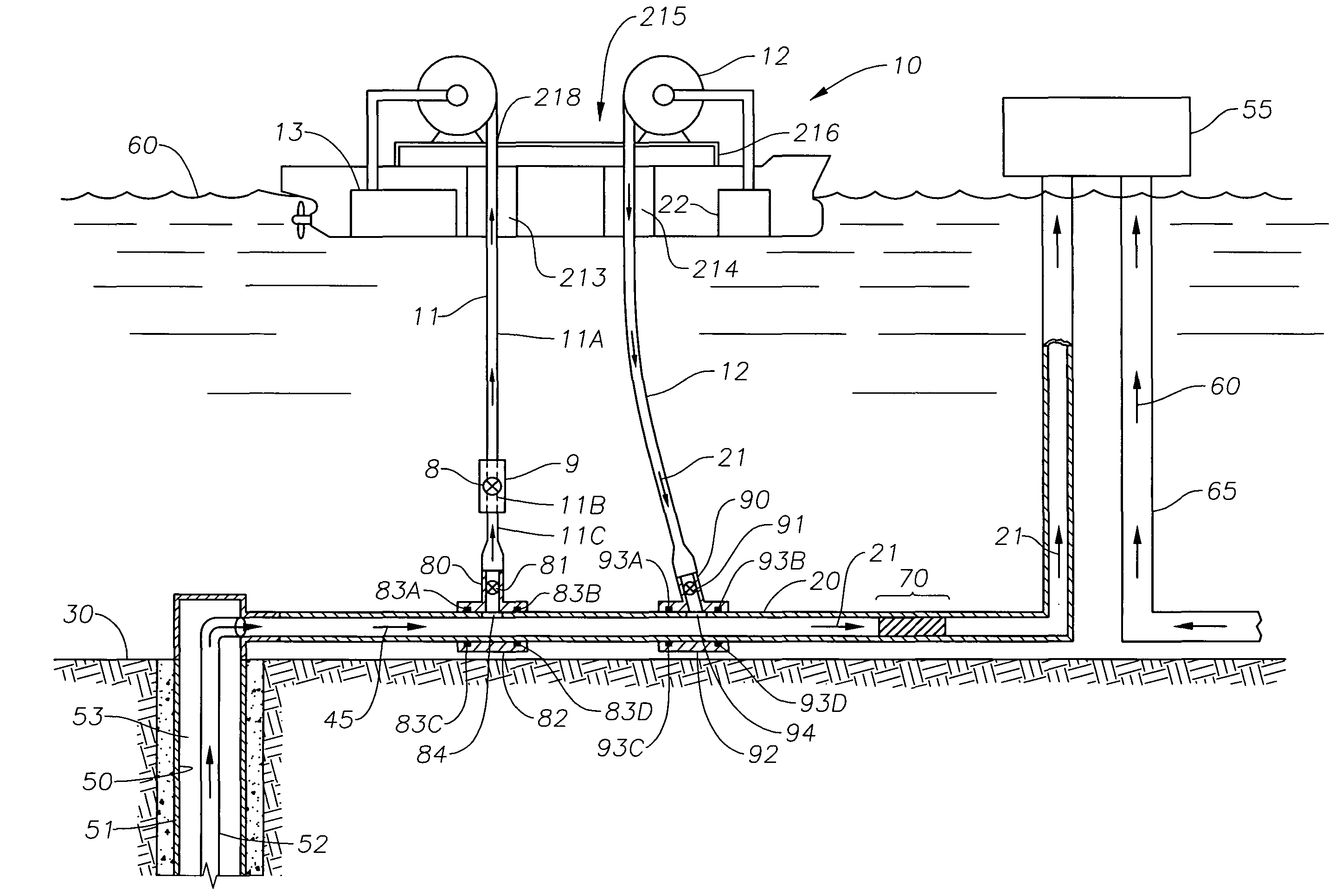
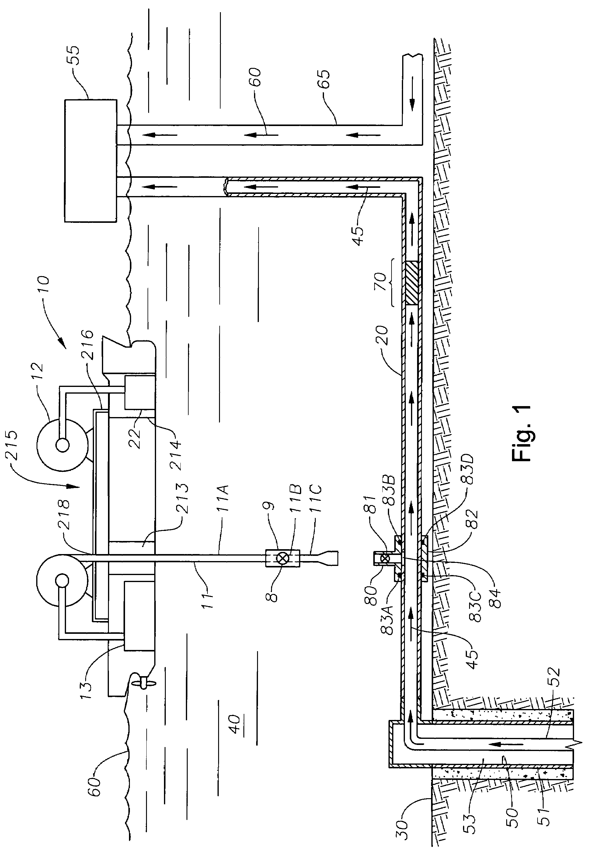
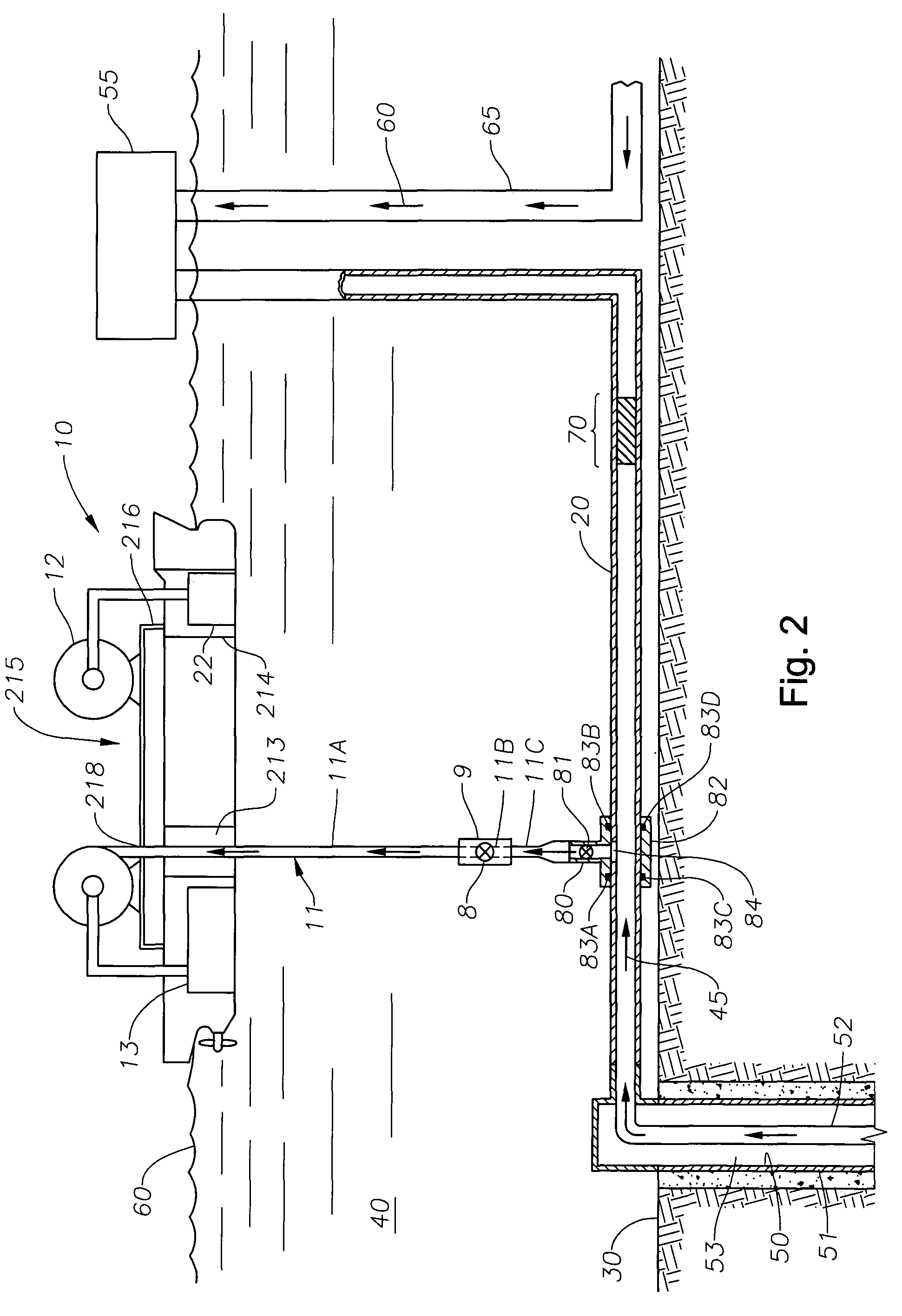
[0024]In another aspect, the present invention provides an apparatus for remediating an offshore pipeline and producing well fluids, comprising a vessel capable of storing well fluids flowing through the pipeline from a well, a first tubular body disposed within the vessel for diverting well fluid flow from the pipeline to the vessel for storing, and a second tubular body disposed within the vessel for remediating the pipeline. The vessel may be capable of diverting well fluid flow through the first tubular body while remediating the pipeline through the second tubular body and capable of remediating the pipeline without interruption of production of well fluids.
[0027]The present invention advantageously allows offshore or subsea intervention operations to occur within a pipeline while simultaneously producing hydrocarbons from the pipeline, thus increasing profitability of the wellbore. Further, the present invention permits formation of an offshore or subsea cased wellbore with one run-in of the casing, and also allows for storage and / or processing of hydrocarbons during the drilling process on the same vessel which houses the equipment used to form the cased wellbore, increasing the profitability of the wellbore.

Problems solved by technology

When forming a subsea wellbore, the initial length of wellbore that has been drilled is subject to potential collapse due to soft formations present at the ocean floor.
Additionally, sections of wellbore that intersect areas of high pressure can cause damage to the wellbore during the time lapse between the formation of the wellbore and the lining of the wellbore.
Offshore production operations, however, require alternative storage and processing methods because of the limited space allotted to hydrocarbon production at the surface of a body of water.
Because drilling rigs are relatively expensive to maintain above the wellbore after the completion operation, the drilling rig is removed from its location above the completed wellbore and employed to drill a subsequent wellbore at a different location.
At this point, production of the hydrocarbons and subsequent storage of the hydrocarbons becomes an issue.
The production platform is usually not large enough to accommodate the large volume of hydrocarbons which flow through the production tubing to the production platform; therefore, the production platform must only store hydrocarbons until a tanker arrives to transport the hydrocarbons from the storage unit to a larger storage and processing unit at another location.
This method is expensive because each production platform above each wellbore which must be constructed and maintained represents a relatively large expense.
Special problems are currently encountered when satelliting.
Because of the cold temperatures within the water, flowing the liquid hydrocarbons underwater for long distances is often challenging.
One problem which may result from the cold temperature of the water involves the viscosity of the hydrocarbons.
Therefore, the colder the water surrounding the pipelines becomes, the more difficult or impossible flowing the hydrocarbons from the wellbore to the storage unit becomes.
Decreasing viscosity of the liquid hydrocarbons flowing in the pipeline may ultimately cause blockage within the pipeline, reducing or halting hydrocarbon production.
A second problem which may result from the cold temperature of the water involves the changing temperatures of the hydrocarbons during their production.
These temperature variations when using pipeline to transport produced hydrocarbons to the satellite unit often result in precipitation of the hydrocarbons on the inside of the pipeline.
Eventually, the precipitation build-up may result in partial or total blockage of the flow path through the pipeline, decreasing or stopping hydrocarbon production.
Reduced hydrocarbon production decreases the profitability of the wellbore.
Other problems which require pipeline intervention to reduce blockage include paraffin deposits which often build up in the pipelines due to the presence and flow of oil, as well as gas hydration when gas is present in the hydrocarbon stream.
Pipeline intervention operations are costly.
Stopping the flow of the hydrocarbons reduces the profitability of the well, as the equipment and labor required to produce the hydrocarbons is still funded while no hydrocarbon production is occurring to offset these costs.
Such vessels, however, cannot be considered appropriate platforms for interventions requiring drilling or hydrocarbon production as they are not sufficiently stable for such operations and are too small to handle the volumes of material that result from drilling.
Furthermore, light intervention vessels require large capital investments as compared with the returns that can be generated, particularly as they are highly vulnerable to bad weather such that intervention costs are relatively high and utilization time is relatively low.
Even more cost is required to employ an additional support vessel.
Because of the above disadvantages, no attempts have been made to use continuous casing to drill and line a wellbore from floating units or to allow hydrocarbon production during intervention operations in offshore wells.

Method used


Image

  • Vessel for well intervention
  • Vessel for well intervention
  • Vessel for well intervention

Examples


Embodiment Construction

[0039]FIG. 8 illustrates a vessel 10 embodying the present invention. FIG. 8 is based on a drawing extracted from “First Olsen Tankers” and shows a shuttle tanker of the type widely used in the North Sea. In the vessel 10, the only modification made to the standard shuttle tanker is the mounting of a superstructure 107 above the main deck (not shown) of the vessel 10, for example at a height of approximately 3 meters so as to exist above the installed deck pipes and vents (not shown). A standard North Sea specified shuttle tanker with dynamic positioning can be readily charted and fitted with a new deck above the installed deck pipes and vents, upon which deck can be installed, for example, the following equipment: a skid mounted derrick riser handling unit with subsea control panel; stumps for the subsea well intervention equipment; a pipe rack; coiled tubing reels, a control unit, and a power pack; a cementing unit and blender, production test equipment including a choke manifold,...


PUM


Abstract

In one aspect, a method and apparatus for intervening in an offshore pipeline while diverting fluid flow to a storage site is provided, so that production through the offshore pipeline may continue while conducting a pipeline intervention operation. An offshore vessel may be used to divert and store fluid flow while intervening in the pipeline. In another aspect, a method and apparatus for drilling a subsea wellbore with an offshore vessel is provided. The method and apparatus involve drilling the wellbore and casing the wellbore with continuous casing lowered from the offshore vessel.

Description

BACKGROUND OF THE INVENTION[0001]1. Field of the Invention[0002]Embodiments of the present invention generally relate to an apparatus and method for intervening in offshore pipelines. Embodiments also relate to an apparatus and method for drilling and casing an offshore wellbore.[0003]2. Description of the Related Art[0004]Hydrocarbon production occurs either directly from the earth or from the earth below a body of water. Production directly from the earth is typically termed a “land production operation,” while production from the earth below a body of water is ordinarily typically termed an “offshore production operation” or a “subsea” production operation.” To obtain hydrocarbons in either a land production operation or an offshore production operation, casing is inserted into a drilled-out wellbore within the earth formation. Casing isolates the wellbore from the formation, preventing unwanted fluids such as water from flowing from the formation into the wellbore. The casing is...

Claims


Application Information

Patent Timeline
Patent Type & Authority Patents(United States)
IPC IPC(8): E21B33/00B23B41/08F16L55/18B63B27/24B63B35/00B63B35/44E21B7/20E21B10/64E21B21/00
CPCB63B27/24B63B35/00B63B35/4413E21B10/64E21B7/203Y10T137/0458E21B2021/006E21B21/085
Inventor BOYLE, JOHN
Owner WEATHERFORD TECH HLDG LLC
Learn More