Devices, systems and methods for material fixation

a technology of material fixation and devices, applied in the field of devices, systems and methods for material fixation, can solve the problems of difficulty in traditional techniques used to fix tendons to bone, difficulty in repairing, and difficulty in achieving the effect of preventing dislocation of anchors, and sufficient pull-out forces

Inactive Publication Date: 2010-01-26
CAYENNE MEDICAL INC
View PDF158 Cites 80 Cited by
  • Summary
  • Abstract
  • Description
  • Claims
  • Application Information

AI Technical Summary

Benefits of technology

[0014]In examples described through this disclosure, the present invention is shown as a tendon to bone fixation using a device that is easy to manufacture and use. In particular embodiments, the present invention is a modified anchor. The elegant simplicity of this invention eases the complexity of tenodesis procedures and its basic but effective design and use will make it readily adopted by the orthopedic community.
[0017]Exemplary anchor embodiments of the present invention provide for a substantially non-cylindrical shape having a substantially non-circular cross-section to enable compression of the graft directly against bone and securing the anchor within the bone tunnel. The substantially non-cylindrical geometry applies differential forces to compress the graft against bone tissue versus affixing the anchor within the bone tunnel. As such, the substantially non-cylindrical anchor embodiments are able to urge the graft directly against bone tissue without damaging, abrading, or tearing the graft while maintaining sufficient pull-out forces by engaging the bone tissue directly to prevent dislodgement of the anchor relative to the bone. This separation of applied forces results from the non-cylindrical geometry of the substantially non-cylindrical anchor embodiments.
[0018]Exemplary device embodiments of the present invention offer distinct advantages over current techniques. Compared to other conventional devices, such as, for example, ones described above, the present devices offer, for example, ease of insertion (no preparation of tendon end required, single handed trigger deployment), minimization of graft trauma (no rotation of tendon upon insertion, no cutting of graft with screw threads, no cutting sutures), a substantially non-cylindrical cross-section to improve fixation and graft compression, and facilitation of graft tensioning.
[0019]Compared to standard interference screw fixation, the embodiments of the invention allow direct fixation of the tendon, or other graft within the bone tunnel without a pull-through stitch needed to seat the tendon into the bone tunnel and hold tension during fixation. By further comparison to traditional techniques, the present device eliminate the need for bone tunnel preparation and the subsequent need to thread sutures and tendon through these bone tunnels. By providing aperture fixation, the embodiments of the invention minimize graft motion in the tunnels, thereby eliminating the “bungee effect” and “windshield wiper effect”. Finally, they provide direct tendon to bone compression, which facilitates healing, and provides a single point of fixation, which allows for more isometric graft positioning.
[0020]Many advantages of the present invention, as shown in its various embodiments, are apparent to one having ordinary skill in the art. General categories of non-limiting examples of the advantages of the present invention include, but are not limited to: ease of preparation, ease of insertion and lack of tendon compromise. There is ease of preparation because there are no bone tunnels, minimal exposure required, and no tendon preparation (whip-stitch) needed. There is ease of insertion because there are no passing sutures through tunnels, no threading tendon through tunnels, and single handed insertion and deployment. Finally, there is no tendon compromise because there is no cutting of the graft with screw threads, and no cutting of the sutures with screw threads. These and other advantages of the present invention are described herein and apparent to those having ordinary skill in the art.

Problems solved by technology

In addition, tendons which are torn from their insertion site into bone also frequently require repair.
Traditional techniques that are used to fix tendon to bone suffer from a number of limitations as a result of the methodology used, including the use of a “keyhole” tenodesis, pull-out sutures, bone tunnels, and interference screw fixation.
This technique is challenging as it is often difficult to sculpt the keyhole site and insert the tendon into the tunnel.
In addition, if the tendon knot unravels in the postoperative period, the tendon will slide out of the keyhole, losing fixation.
This technique has lost favor in recent years due to a host of associated complications, which include wound problems, weak fixation strength, and potential injury to adjacent structures.
The creation of bone tunnels is relatively complicated, often requiring an extensive exposure to identify the margins of the tunnels.
This tedious process is time-consuming and fraught with complications, which include poor tunnel placement and fracture of the overlying bone bridge.
Graft isometry, which is easy to determine with single point fixation, is difficult to achieve because the tendon exits the bone from two points.
This portion of the procedure is often time-consuming and frustrating to a surgeon.
Finally, the procedure can be compromised if the bone bridge above the tunnel breaks, resulting in loss of fixation.
The technique restricts fixation to the strength of the sutures, and does not provide any direct tendon to bone compression.
While this technique eliminates the need for secondary incisions to place the post, the fixation strength is limited to suture strength alone.
This technique does not provide direct tendon to bone compression; as such this technique may slow healing and lead to graft tunnel widening due to the “bungee effect” and “windshield wiper effect”.
As a result, this technique has limited clinical applications and is used primarily for salvage when bone tunnels break or backup fixation is important.
Some disadvantages related to soft tissue interference screws are that they can be difficult to use, and can also cut or compromise the tendon during implantation.
While this screw system provides advantages in the insertion of tendon into bone in cases when a pull through stitch is not available, it is still limited by the potential for tendon rotation or disruption as the screw compresses the tendon.
The surgical technique is also complicated, typically requiring two or more hands for insertion, making it difficult to use the system without assistance during arthroscopic or open procedures.
Finally, the use of the screw requires preparation of the tendon end, which can be difficult, time consuming, and can also require conversion of an arthroscopic procedure to open.
Thus, although there are many conventional techniques used for the fixation of tendon to bone, each having some advantages, the disadvantages of each such technique presents a need in the art for a simple and universal technique to fixate tendon to bone such that the device is easy to use, the process is simple to follow, and the result is a firm and secure tendon to bone fixation with minimal negative effect on the tendon.

Method used


Image

  • Devices, systems and methods for material fixation
  • Devices, systems and methods for material fixation
  • Devices, systems and methods for material fixation

Examples


embodiment 71

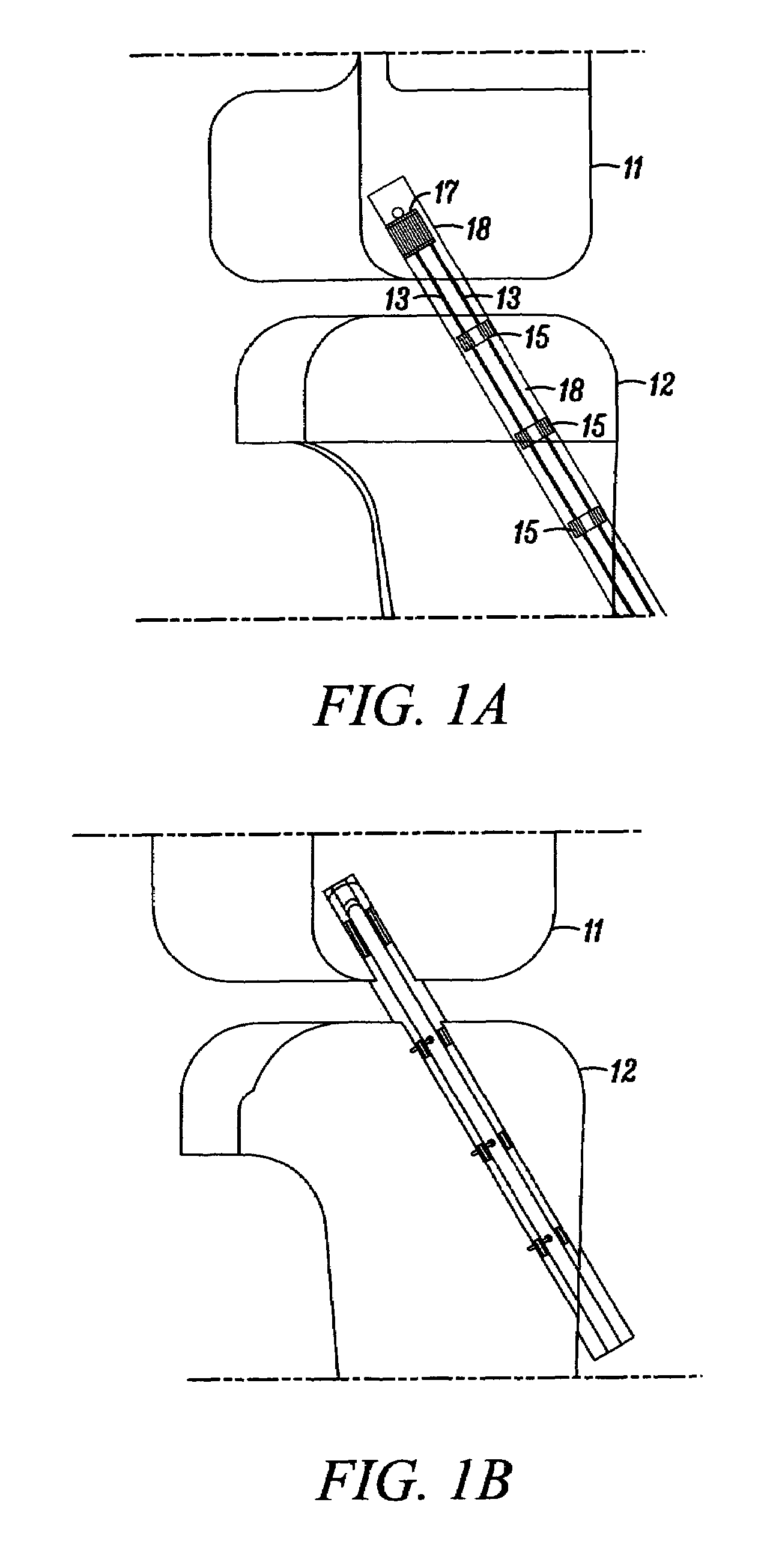
[0137]FIGS. 12A to 12D show an isometric view, a side view, a cross-sectional view, and a side-sectional view of the deployment instrument 41 in FIG. 4A with the substantially non-cylindrical direct anchor embodiment 71 of FIGS. 7 and 8 positioned for placement. As shown in FIGS. 12B and 12D, the deployment instrument 41 is positioned between the strands 122 of the ACL graft free ends to secure the ACL graft 122 to the tibia 121. After placement, the dilator 45 is actuated thereby expanding the direct anchor 71 inside the drilled bone hole 123, compressing the tendon free ends 122 against the bone surface defined by the drilled hole 123 and engaging the securing extensions of the direct anchor 71 against the bone 121.

[0138]FIGS. 13A to 13D show exemplary steps for deploying and attaching a strand of tendon or graft within a drilled bone hole. The deployment instrument 41 of FIG. 4A is used to insert the looping strand 132 of tendon and the direct anchor 139 into a predrilled bone ho...

embodiment 141

[0139]FIGS. 14A to 14D show two isometric views, a side view, and a side-sectional view, respectively, of an alternative deployment instrument embodiment 141 according to the present invention. This deployment instrument 141 uses an anvil 142 to support the direct anchor 143 while a shaft 144 incorporating an expansion transition is actuated and advanced relative to the direct anchor 143. Once actuated, the expansion shaft 144 is used to expand the direct anchor 143 into a radially enlarged orientation. Once fully expanded into the bone hole, the anvil 142 releases from the central lumen of the direct anchor 143 signaling full expansion of the direct anchor 143 thus completing attachment of the tendon(s) to the surface of the bone defined by the drilled hole. Until the direct anchor 143 is fully expanded, the anvil 142 supports the direct anchor 143 as the expansion shaft 144 continues to move axially further expanding the direct anchor 143.

[0140]This exemplary deployment instrument...

embodiment 191

[0145]FIGS. 19A and 19B show an isometric and a top view of an alternative substantially non-cylindrical direct anchor embodiment 191 that incorporates “butterfly” extensions 192 that engage the surface of the bone defined by the drilled hole, and slots 193 that create flaps 194 that, once positioned and actuated, engage either the tendon and / or the surface of the bone defined by the drilled hole to increase the bond strength between the substantially non-cylindrical direct anchor 191 and the tendon to the bone.

[0146]FIGS. 19C and 19D show an isometric view and a top view of the substantially non-cylindrical direct anchor embodiment 191 in FIGS. 19A and 19B in an expanded orientation with the substantially non-cylindrical direct anchor 191 fully deformed to compress tendon against the surface of the bone defined by the drilled hole and engage the bone anchor to that surface.

[0147]FIGS. 20A and 20B show isometric views of two alternative direct anchor embodiments 201 and 205 that inc...


PUM


Abstract

Devices, systems and methods for fixation of tendon to bone are described. An exemplary surgical implant is a modified bone anchor that is able to grasp the tendon and hold it firmly in a bone tunnel. Once deployed, the anchor delivers lateral compression to the tendon, providing direct tendon to bone compression to facilitate healing. The anchor has different versions which allow it to be attached to the tendon prior to insertion into the bone tunnel, or be inserted between tendon arms when the surgical procedure dictates. The resulting tendon to bone compression allows for the firm fixation in a manner markedly simpler than traditional techniques. A modification of this anchor can also allow the anchor to grasp and hold suture. This variation facilitates the technique for knotless rotator cuff repair.

Description

[0001]This U.S. Utility Patent Application claims priority to U.S. Provisional Patent Application Ser. No. 60 / 628,774, filed Nov. 18, 2004, and U.S. Provisional Patent Application Ser. No. 60 / 671,510, filed Apr. 15, 2005, the contents of each of which are hereby incorporated by reference in their entirety into this disclosure.BACKGROUND OF THE INVENTION[0002]1. Field of the Invention[0003]The present invention relates generally to devices, systems and methods for material fixation. More specifically, the present invention relates to a technique that can be used to firmly hold a soft tissue or graft against bone tissue within a bone tunnel.[0004]2. Background of the Invention[0005]One of the most common needs in orthopedic surgery is the fixation of tendon to bone. The fixation of diseased tendons into a modified position is called tenodesis and is commonly required in patients with injury to the long head of the biceps tendon in the shoulder. In addition, tendons which are torn from...

Claims


Application Information

Patent Timeline
Patent Type & Authority Patents(United States)
IPC IPC(8): A61F2/08
CPCA61B17/0401A61F2/0811A61B2017/00862A61B2017/0409A61B2017/0412A61B2017/0414A61B2017/0435A61B2017/0437A61F2/0805A61F2002/0852A61F2002/0858A61F2002/0882A61F2002/0888
Inventor MONTGOMERY, KENNETH D.FLEISCHMAN, SIDNEY D.WHAYNE, JAMES G.OHASHI, KEVIN L.DOMINGO, NICANORWRIGHT, JOHNHARPER, DEREK J.CROCKETT, HEBER
Owner CAYENNE MEDICAL INC
Why Eureka
Try Eureka